BER of 3 user Non-orthogonal multiple access (NOMA) with QPSK modulation
In a previous post, we saw how to plot the bit error rate (BER) of a two user NOMA. There, we used BPSK modulation for both the users. Can we multiplex more than two users in a single carrier in NOMA? Of course. In this post, we are going to multiplex three users, each following QPSK modulation, in a single frequency carrier.
System Model
Let us consider a wireless network consisting of three NOMA users, numbered U1, U2 and U3. Let $d_1$, $d_2$ and $d_3$ denote their respective distances from the base station (BS) such that, $d_1 \gt d_2 \gt d_3$. Based on their distances, U1 is the weakest/farthest user and U3 is the strongest/nearest user to the BS.
Let $h_1$, $h_2$, and $h_3$ denote their corresponding Rayleigh fading coefficients such that, $|h_1|^2 \lt |h_2|^2 \lt |h_3|^2$ . (The channels are ordered this way because $h_i \propto \dfrac{1}{d_i}$)
Let $\alpha_1$, $\alpha_2$ and $\alpha_3$ denote their respective power allocation coefficients. According to the principles of NOMA, the weakest user must be allocated the most power and the strongest user must be allocated the least power. Therefore, the power allocation coefficients must be ordered as $\alpha_1 \gt \alpha_2 \gt \alpha_3$. The choice of power allocation coefficients has a great significance on the performance of a NOMA network. In this post, for simplicity, we are using fixed power allocation. There are several dynamic power allocation schemes available, that would give better performance.
Signal Model
Let $x_1$, $x_2$ and $x_3$ denote the QPSK modulated messages that the BS needs to send to U1, U2 and U3 respectively. Then, the superposition coded signal transmitted by the BS is given by, $$x = \sqrt{P}(\sqrt{\alpha_1}x_1+\sqrt{\alpha_2}x_2+\sqrt{\alpha_3}x_3)$$ The signal received at the $i^{th}$ user is given by, $$y_i = h_ix + n_i$$ where $n_i$ denotes AWGN at receiver of Ui.SIC Decoding procedure
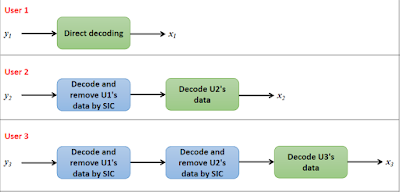
At User 1
Since U1 is allocated the highest power, he will perform direct decoding from $y_1$, treating the signals of U2 and U3 as interference. Thus, the achievable rate of U1 is, $$R_1 = log_2\left(1 + \dfrac{\alpha_1P|h_1|^2}{\alpha_2P|h_1|^2+\alpha_3P|h_1|^2+\sigma^2}\right)$$ which can further be simplified as, $$R_1 = log_2\left(1 + \dfrac{\alpha_1P|h_1|^2}{(\alpha_2+\alpha_3)P|h_1|^2+\sigma^2}\right)$$ From the above equation, we make one important observation. Since $\alpha_2 + \alpha_3$ is present at the denominator, now we want $\alpha_1$ to satisfy $\alpha_1 \gt \alpha_2 + \alpha_3$. Only then, U1's power will dominate in the transmit signal, $x$ and in the received signal, $y_1$.
At User 2
Next let's write the rate equation for U2. Since $\alpha_2 \lt \alpha_1$ and, $\alpha_2 \gt \alpha_3$, U2 must perform successive interference cancellation to remove U1's data and treat U3 as interference. After removing U1's data by SIC, the achievable rate for U2 is, $$R_2 = log_2\left(1 + \dfrac{\alpha_2P|h_2|^2}{\alpha_3P|h_2|^2 + \sigma^2}\right)$$ Since $\alpha_3$ is present in the interference term at the denominator, we want $\alpha_2$ to satisfy $\alpha_2 \gt \alpha_3$.
At User 3
Finally, U3 ($\alpha_3 \lt \alpha_1$, $\alpha_3 \lt \alpha_2$,) has to perform SIC two times to remove both U1 and U2 data from $y_3$. Since the $\alpha_1$ term dominates in $y_3$, it must be removed first. After that, the $\alpha_2$ term must be removed. The achievable rate is, $$R_3 = log_2\left(1 + \dfrac{\alpha_3P|h_3|^2}{\sigma^2}\right)$$
MATLAB Simulation
Let's simulate the BER vs transmit power characteristics of this system using MATLAB.
1. First, let's set our simulation parameters: Distances are set as $d_1 = 500m$, $d_2 = 200m$, $d_3 = 70m$. The power allocation coefficients are set as $\alpha_1=0.8$, $\alpha_2 = 0.15$, $\alpha_3 = 0.05$. These values satisfy the conditions $\alpha_1 \gt \alpha_2 \gt \alpha_3$ and, $\alpha_1 \gt \alpha_2 + \alpha_3$. Set path loss exponent.
        d1 = 500; d2 = 200; d3 = 70;       %Set distances
        a1 = 0.8; a2 = 0.15; a3 = 0.05;    %Power allocation coefficients
eta = 4; %Path loss exponent2. Set the transmit power range (here, we have used 0 to 40 dBm). Convert the transmit power from dBm to linear scale for future calculations.
        Pt = 0:40                   %Transmit power in dBm
        pt = (10^-3)*db2pow(Pt);    %Transmit power in linear scale
3. Generate Rayleigh fading coefficients $h_1$, $h_2$, $h_3$ for each user using the command:
        h1 = sqrt(d1^-eta)*(randn(N/2,1) + 1i*randn(N/2,1))/sqrt(2);
        h2 = sqrt(d2^-eta)*(randn(N/2,1) + 1i*randn(N/2,1))/sqrt(2);
        h3 = sqrt(d3^-eta)*(randn(N/2,1) + 1i*randn(N/2,1))/sqrt(2);
Here, N is the number of bits to be transmitted. Since we are using QPSK modulation, each symbol has 2 bits. Therefore, we are going to transmit N/2 symbols. For each symbol, we are generating a Rayleigh fading coefficient.
Also, $d_i^{-\eta}$ is the variance of $h_i$, and its mean is zero
4. Define the amount of noise power. For that, let's consider a bandwidth of 1 MHz. As we know, the thermal noise power is given by, kTB. For a bandwidth of 1 Hz, the noise power is $log_{10}(kT) = - 174$ dBm. So, for 1 MHz bandwidth, the noise power will be $-174 + log_{10}(1MHz)$.
        BW = 10^6;                    %Bandwidth
        No = - 174 + 10*log10(BW);    %Noise power in dBm
        no = (10^-3)*db2pow(No);      %Noise power in linear scale
5. Using the noise power calculated in step 3, let's generate noise samples for all the three users by using the following command:
        n1 = sqrt(no)*(randn(N/2,1) + 1i*randn(N/2,1))/sqrt(2);
        n2 = sqrt(no)*(randn(N/2,1) + 1i*randn(N/2,1))/sqrt(2);
        n3 = sqrt(no)*(randn(N/2,1) + 1i*randn(N/2,1))/sqrt(2);
n1, n2 and n3 have mean zero and variance no, This no is the $\sigma^2$ that we used in the equations.
6. Generate random message bits for users using the following command:
        x1 = randi([0 1],N,1);
        x2 = randi([0 1],N,1);
        x3 = randi([0 1],N,1);
7. Do QPSK modulation for each user's message. For this, we are going to use MATLAB's in-built QPSKModulator object. This will greatly simplify our modulation and demodulation part. First, we have to create the QPSKModulator and QPSKDemodulator object as follows:
        QPSKmod = comm.QPSKModulator('BitInput',true);       %Modulator object
        QPSKdemod = comm.QPSKDemodulator('BitOutput',true);  %Demodulator object
QPSKmod and QPSKdemod are our modulator and demodulator objects. We have set the argument 'BitInput' as true because we are going to feed raw binary data.
Using our QPSKmod object to perform modulation is very simple. We use the step function and, in its argument, pass our QPSKmod object and the binary bit stream to be modulated.
        xmod1 = step(QPSKmod, x1);
        xmod2 = step(QPSKmod, x2);
        xmod3 = step(QPSKmod, x3);
8. Do superposition coding to create the NOMA transmit signal
x = sqrt(a1)*xmod1 + sqrt(a2)*xmod2 + sqrt(a3)*xmod3;
9. Iterate over every value of transmit power: ('u' is used as the iteration variable)
for u = 1:length(Pt)
(i) Write received signal equation for all the three users
               y1 = sqrt(pt(u))*x.*h1 + n1;
               y2 = sqrt(pt(u))*x.*h2 + n2;
               y3 = sqrt(pt(u))*x.*h3 + n3;
(ii) Perform equalization by dividing each received signal with the respective user's fading coefficient
               eq1 = y1./h1;
               eq2 = y2./h2;
               eq3 = y3./h3;
(iii) First, lets do the processing at the receiver side of U1. Directly demodulate eq1 to get x1. To do this, we use the QPSKDemodulator object we created as follows:
dec1 = step(QPSKdemod, eq1);
(iv) Moving on to U2. First, directly decode x1 from eq2.
dec12 = step(QPSKdemod, eq2);dec12 is in 0's and 1's. Before subtracting dec12 from eq2, we must first remodulate it to convert it to the same form as in eq2. So, let's do that.
dec12_remod = step(QPSKmod, dec12);
Now, we can perform SIC to remove our estimate of U1's data (i.e., dec12_remod) from eq2, as shown:
rem2 = eq2 - sqrt(a1*pt(u))*dec12_remod;
rem2 contains U2 and U3's data. Do direct QPSK demodulation on rem2 as before, to get U2's data.
(v) Moving on to U3. First direct decode x1 from eq3. Remodulate the estimate of x1 that is obtained and subtract it from eq3.
               dec13 = step(QPSKdemod, eq3);
               dec13_remod = step(QPSKmod, dec13);
               rem31 = eq3 - sqrt(a1*pt(u))*dec12_remod;
Again, demodulate rem31 to get x2. Remodulate the estimate of x2 and subtract it from rem31.
               dec23 = step(QPSKdemod, rem31);
               dec23_remod = step(QPSKmod, dec23);
               rem3 = rem31 - sqrt(a2*pt(u))*dec23_remod;
dec3 = step(QPSKdemod, rem3); %Demodulate rem3 to get dec3
(vi) BER calculation. For this, we use MATLAB's inbuilt biterr() function.
               ber1(u) = biterr(dec1, x1)/N;
               ber2(u) = biterr(dec2, x2)/N;
               ber3(u) = biterr(dec3, x3)/N;
end for loop.
(vii) Plot the BER vs transmit power graphs of all the three users. We get a graph like this

We can see that the user 1 has the highest BER among the three. That is because he suffers the most interference. That is, both User 2 and User 3 cause interference for User 1. User 2 suffers moderate interference due to User 3. Finally, User 3 is free from interference and has the lowest BER in the group.
The BER performance is also strongly affected by the power allocation scheme that is used. Here, we have used fixed power allocation, which is not the best solution. If we resort to more sophisticated power allocation schemes, we may see further improvement in performance.


Thanks a lot for the explanation it's very helpful the code is really good and simple to be understood.
ReplyDeleteThats great. Can we also incorporate the 'Fair power allocation' you used in previous post for three users ? and if yes, how we can do that?. Also would you try to include MIMO in future posts. I think that would be interesting. Thank you for your efforts in this topic once again.
ReplyDeleteThere we derived alpha 1 and alpha 2 specifically for a two user case. I think when multiple users are involved, the power allocation would become even more complicated. So we cannot apply 'fair PA' as such...
DeleteSure! we will see the combination of NOMA with MIMO in a future post. thank you
will you please share NOMA with OFDM code
DeleteYour codes and explanation are really soo helpful. Thank you so much. I wanted to ask you a doubt regarding a code. Can you please share your email id.
ReplyDeleteHi, Glad to know you found the blog useful
DeleteHere's my mail id:
electronicswithme@gmail.com
Hi...do you have the code for SCMA, LDS-CDMA and LDS-OFDM?
ReplyDeleteHi, I don't have those codes right now. If I did write them, I'd notify you here
DeleteCan you explain to me about perform equalization by dividing each received signal with the respective user's fading coefficient? what does that mean?
ReplyDeleteeq1 = y1./h1;
eq2 = y2./h2;
Thank you!
Due to fading, every bit undergoes random amplitude and phase changes. We model this by multiplying the transmit signal with 'h (Rayleigh fading coefficient)'. This is an undesirable effect and must be removed.
DeleteIf we have perfect knowledge about the channel, i.e., if we know 'h' at the receiver, the effect of fading can be undone by dividing the received signal with 'h'.
Hello Joe can you explain step 3 plz the Rayleigh channel parameters?? Thanks in advance
ReplyDeleteHi Rania,
DeleteWe want every transmit symbol to undergo a random amplitude and phase change. Since we are doing QPSK modulation, we will be transmitting N/2 symbols.
The (randn(N/2,1)+1i*randn(N/2,1)) generates N/2 Rayleigh fading coefficients, one for each symbol that is transmitted.
Next, we have to set the mean and variance of our Rayleigh fading coefficients as we desire.
We want the mean to be zero. randn() automatically generates zero mean random variables so we don't have a problem there
Now, the variance. We want the variance to be [distance^-(path loss exponent)]. randn() generates random variables with variance 1. Hence, [randn()+1i*randn()] will have variance 2. So, first are dividing by sqrt(2) to make it have unit variance. Then, we are multiplying by [sqrt{distance^-(path loss exponent)}] to get the desired variance.
Hope this helps
Thank you Joe.
DeleteIn this example the Pt range is 0:40 how to get the SNR range for the same transmitted power range so that I can plot BER vs SNR.
ReplyDeleteIn the code, noise power was set as -114dBm. So, the transmit SNR will be
DeletePt - (-114) dB
This is my code for QPSK for SNR VS BER where i am wrong?
Deleteclc; clear variables; close all;
N = 5*10^5;
Pt=0:40;
pt = (10^-3)*db2pow(Pt);
SNR_dB = Pt-(-114) ; %Transmit power (dBm)
EbN0 = SNR_dB+10*log10(SNR_dB); %Transmit power (linear scale)
BW = 10^6; %Bandwidth = 1 MHz
No = -174 + 10*log10(BW); %Noise power (dBm) %
no = (10^-3)*db2pow(No); %Noise power (linear scale)
d1 = 4; d2 = 2; %Distances
a1 = 0.8; a2 = 0.2; %Power allocation coefficients
eta = 4; %Path loss exponent
%Generate Rayleigh fading channel for the three users
h1 = sqrt(d1^-eta)*(randn(N/2,1) + 1i*randn(N/2,1))/sqrt(2);
h2 = sqrt(d2^-eta)*(randn(N/2,1) + 1i*randn(N/2,1))/sqrt(2);
%Generate noise samples for the three users
n1 = sqrt(no)*(randn(N/2,1) + 1i*randn(N/2,1))/sqrt(2);
n2 = sqrt(no)*(randn(N/2,1) + 1i*randn(N/2,1))/sqrt(2);
%Generate random binary message data for the three users
x1 = randi([0 1],N,1);
x2 = randi([0 1],N,1);
x3 = randi([0 1],N,1);
%Create QPSKModulator and QPSKDemodulator objects
QPSKmod = comm.QPSKModulator('BitInput',true);
QPSKdemod = comm.QPSKDemodulator('BitOutput',true);
%Perform QPSK modulation
xmod1 = step(QPSKmod, x1);
xmod2 = step(QPSKmod, x2);
%Do super position coding
x = sqrt(a1)*xmod1 + sqrt(a2)*xmod2;
for u = 1:length(SNR_dB)
%Received signals
y1 = sqrt(pt(u))*x.*h1 + n1; %At user 1
y2 = sqrt(pt(u))*x.*h2 + n2; %At user 2
%Perform equalization
eq1 = y1./h1;
eq2 = y2./h2;
%Decode at user 1 (Direct decoding)
dec1 = step(QPSKdemod, eq1);
%Decode at user 2
dec12_remod = step(QPSKmod, dec1); %Remodulation of U1's data
rem2 = eq2 - sqrt(a1*pt(u))*dec12_remod; %SIC to remove U1's data
dec2 = step(QPSKdemod, rem2); %Direct demodulation of remaining signal
%BER calculation
b1(u) = biterr(dec1, x1)/length(dec1);
b2(u) = biterr(dec2, x2)/length(dec2);
end
ber1(u)=mean(b1);
ber2(u)=mean(b2);
figure,
semilogy(SNR_dB, ber1, 'ro', 'linewidth', 2); hold on; grid on;
semilogy(SNR_dB, ber2, '-mx', 'linewidth', 2);
xlabel('Transmit power (dBm)');
ylabel('BER');
%axis([0 40 10^-3 10^3]);
legend('User 1 (Weakest user)', 'User 2', 'User 3 (Strongest user)');
Your codes and explanation are super easy to understand. Thank you so much. I wonder if you have code for SIC using MMSE or Zero Forcing by any chance?
ReplyDeleteHi, glad you found the blog useful.
DeleteRight now I dont have those codes. If I did write them, I'd notify you here
Oh! Thank you very much!
Deletewhat the difference in case using 16-QAM and ldpc codes
DeleteI dont think that equalization can be done by simply dividing channel coefficients..
ReplyDeleteSimple multiplication and division cannot model channel effects. Comm channels are multiplied in frequency domain and convolved in time domain. Simplest of the equalization, zero forcing equalization requires conversion of received signal in frequency domain and multiplication with inverse frequency response of channel.
hi,
ReplyDeletepleas help me I need matlab code of d2d communication in NOMA
thanks
Hi!
ReplyDeleteDo you maybe know if the same process of decoding signal (demodulating) also works for PI/4-QPSK? I tried to implement it in C++ with already prepared PI/4-QPSK modulator and demodulator (I think there is no issue with them because modulating and then demodulating single signal works perfectly fine, but when I try to demodulate the summed 3 signals around 1/4 of all bits are wrong in result.
Thanks in advance ^^
Hi, the decoding process is same for all modulation schemes.
DeleteI am not sure why your are getting error, but here's are a few things that I would check:
1. Choice of power allocation. Is a1>a2>a3? AND a1>a2+a3?
2. In the SIC process, after decoding the first signal, it must be remodulated using the same modulation scheme before subtracting it from the total signal
Hope this helps..
ReplyDeletehello Joe in your work you have used BPSK and QPSK modulations which one is most useful in NOMA transmission?
Hi Rania, it depends on the application. But since the far user has lower achievable rate than the near user, we can choose lower order modulation for the far user and higher order modulation for the near user.
DeleteI want to know that if we superpose two packets (primary and secondary, such that primary is provided more power than the secondary one) and then transmit through a Rayleigh fading channel. On the receiver side, if the primary packet is error free, the secondary packet is also decoded using SIC process. Otherwise a second transmission for the primary packet is asked. The transmitter sends the same primary packet but with different power levels, but again the power of the primary packet is more than the secondary packet. Once again the primary and secondary packets are same. Now on the receiver side, the primary packets (received in previous time and current time) are combined using MRC. After MRC I want to equalize the combined packet. I am trying to find the equalizer for it and but to no avail. Please guide me that how can i equalize the combined packet.
ReplyDeleteHi, did you try equalizing the individual received signals first and then combining them?
DeleteHi Mr.Joe
ReplyDeletefirst thanks for this job it's amazing
second i have question plz reply quickly bro
in your code user 1 is the far user so it have the big power and factor ( 0.8 ) so 80% of the power go to the user 1
so how user 1 have the most poor BER ??
user 1 must have the best BER
is that wrong in the code ? or i dont understand something or what ?
plz reply
thanks
Hi Abdelrahim, the near user has a good channel with the Base station, while the far user does not. So, even if a little power is allocated to him, the near user can decode the far user's signal accurately and also do SIC.
Deletehi Joe
Deletei try to do BER for 3 users by using AWGN and BPSK
this is my code
can u tell me what is the wrong ??
clc; clear variables; close all;
N = 10^6; %Number of monte carlo simulations
SNR = 0:30; %SNR range in dB
snr = db2pow(SNR); %SNR range in linear scale
%Generate random data bits for transmission
x1 = randi([0 1],1,N); %Data bits of user 1
x2 = randi([0 1],1,N); %Data bits of user 2
x3 = randi([0 1],1,N); %Data bits of user 3
%Do BPSK modulation of data
xmod1 = 2*x1 - 1;
xmod2 = 2*x2 - 1;
xmod3 = 2*x3 - 1;
%Set power weights for users
a1 = 0.6; a2 = 0.3; a3 = 0.1;
%Do superposition coding
x = sqrt(a1)*xmod1 + sqrt(a2)*xmod2 + sqrt(a3)*xmod3;
%Add AWGN to x (Transmit x through an AWGN channel)
for u = 1:length(snr)
y1 = awgn(x,SNR(u),'measured'); %Received signal at user 1 corrupted by AWGN
y2 = awgn(x,SNR(u),'measured'); %Received signal at user 2 corrupted by AWGN
y3 = awgn(x,SNR(u),'measured'); %Received signal at user 3 corrupted by AWGN
%AT USER 1
%Direct decoding of x from y1
x1_hat = ones(1,N); %just a buffer
x1_hat(y1 < 0) = 0;
%AT USER 2
%Direct decoding of x from y2
x11_est = ones(1,N); %just a buffer
x11_est(y2 < 0) = 0; %Estimate user 1's signal first
x11_est(x11_est == 0) = -1; %Remodulate user 1's signal
%Subtract remodulated x11_est component from y2
rem2 = y2 - sqrt(a1)*x11_est;
%Decode x2 from rem
x2_hat = zeros(1,N);
x2_hat(rem2>0) = 1;
%AT USER 3
%Direct decoding of x from y3
x11_est2 = ones(1,N); %just a buffer
x11_est2(y3 < 0) = 0; %Estimate user 1's signal first
x11_est2(x11_est2 == 0) = -1; %Remodulate user 1's signal
%Subtract remodulated x11_est2 component from y3
rem22 = y3 - sqrt(a1)*x11_est2;
x11_est3 = ones(1,N); %just a buffer
x11_est3(rem22 < 0) = 0; %Estimate user 2's signal first
x11_est3(x11_est3 == 0) = -1; %Remodulate user 2's signal
%Subtract remodulated x11_est3 component from rem22
rem3 = rem22 - sqrt(a2)*x11_est3;
%Decode x2 from rem
x3_hat = zeros(1,N);
x3_hat(rem3>0) = 1;
%Estimate BER
ber1(u) = biterr(x1,x1_hat)/N;
ber2(u) = biterr(x2,x2_hat)/N;
ber3(u) = biterr(x3,x3_hat)/N;
end
%plot BER curves
semilogy(SNR, ber1, 'linewidth', 1.5); hold on;
semilogy(SNR, ber2, 'linewidth', 1.5);
semilogy(SNR, ber3, 'linewidth', 1.5);grid on;
legend('User 1 \alpha_1 = 0.6','User 2 \alpha_2 = 0.3','User 3 \alpha_3 = 0.1');
xlabel('SNR (dB)');
ylabel('BER');
title('BER graph for NOMA in AWGN channel');
bro plz plz plz
Deleteredownload the code of
noma-vs-oma-capacity-comparison
i need some information today plzzzzzzzzzzz
tommorow my supervise need my search for noma ^_^ im waiting u plzzzzzz open it on;y one day them do your edits
Thanks
Hi Abdelrahim,
DeleteThanks for pointing that out.
I was busy and had no time to edit it.
Anyways, I'm publishing it for you (unedited version of course), so you can download the code.
For BER of 3 users code, please try with different power allocation coefficients.
DeleteIt looks like a1 = 0.6; a2 = 0.3; a3 = 0.1; is not optimal here. (Looks like these values create too much interference)
For example, you can try a1 = 0.8; a2 = 0.15; a3 = 0.05;
Hope this helps
hi Mr.Joe
ReplyDeletei tried to do code for 4 users but strange curves appear
can u help plzzzzzzzzzzzzzz
U are the best go ahead
Hi Abdelrahim, I think your problem can be solved by proper choice of power allocation coefficients.
DeleteThis might work:
a1 = 0.75 % or a1 = 0.8;
a2 = (1 - a1)*a1;
a3 = (1 - (a1+a2))*a1;
a4 = (1 - (a1+a2+a3))*a1;
Hope this helps
Yes joe that's help me thanks alot bro
DeleteBut a4 must be equal only
a4=1-(a1+a2+a3)
Thanks u bro
bro i tried to do a comparsion between oma and noma what is the wrong
ReplyDeletehere in our code it is independent distance So how can i do comparsion plzzzzzz tell me
clc; clear variables; close all;
N = 10^5; %Number of monte carlo simulations
SNR = 0:30; %SNR range in dB
snr = db2pow(SNR); %SNR range in linear scale
%Generate random data bits for transmission
x1 = randi([0 1],1,N); %Data bits of user 1
x2 = randi([0 1],1,N); %Data bits of user 2
%Do BPSK modulation of data
xmod1 = 2*x1 - 1;
xmod2 = 2*x2 - 1;
%Set power weights for users
a1 = 0.75; a2 = 0.25;
%Do superposition coding
x = sqrt(a1)*xmod1 + sqrt(a2)*xmod2;
%Add AWGN to x (Transmit x through an AWGN channel)
for u = 1:length(snr)
y1 = awgn(x,SNR(u),'measured'); %Received signal at user 1 corrupted by AWGN
y2 = awgn(x,SNR(u),'measured'); %Received signal at user 2 corrupted by AWGN
%AT USER 1
%Direct decoding of x from y1
x1_hat = ones(1,N); %just a buffer
x1_hat(y1 < 0) = 0;
%AT USER 2
%Direct decoding of x from y2
x11_est = ones(1,N); %just a buffer
x11_est(y2 < 0) = 0; %Estimate user 1's signal first
x11_est(x11_est == 0) = -1; %Remodulate user 1's signal
%Subtract remodulated x11_est component from y2
rem = y2 - sqrt(a1)*x11_est;
%Decode x2 from rem
x2_hat = zeros(1,N);
x2_hat(rem>0) = 1;
%Estimate BER
ber1(u) = biterr(x1,x1_hat)/N;
ber2(u) = biterr(x2,x2_hat)/N;
end
%Set power weights for users
a3 = 0.5; a4 = 0.5;
%Do superposition coding
xmod3 = sqrt(a3)*xmod1;
xmod4 = sqrt(a4)*xmod2;
%Add AWGN to x (Transmit x through an AWGN channel)
for u = 1:length(snr)
y3 = awgn(xmod3,SNR(u),'measured'); %Received signal at user 1 corrupted by AWGN
y4 = awgn(xmod4,SNR(u),'measured'); %Received signal at user 2 corrupted by AWGN
%AT USER 1
%Direct decoding of x from y1
x3_hat = ones(1,N); %just a buffer
x3_hat(y3 < 0) = 0;
%AT USER 1
%Direct decoding of x from y1
x4_hat = ones(1,N); %just a buffer
x4_hat(y4 < 0) = 0;
%Estimate BER
ber1oma(u) = biterr(x1,x3_hat)/N;
ber2oma(u) = biterr(x2,x4_hat)/N;
end
%plot BER curves
or give me code for compastion between OMA & NOMA for BER for 2 or 3 users i will give to my doctor on friday
plz try to help me bro
thanks
Hi Abdelrahim,
DeleteYou can download the code for BER comparison of OMA and NOMA from this link
https://drive.google.com/file/d/1TUi4D_bUIoEw9X74fWQFYkyjNi_n550h/view?usp=sharing
Hope this helps
hi joe
ReplyDeletei need refference to this equation in any paper or book plz
chanel for fading
h1 = (sqrt(d1^-eta))*(randn(N,1) + 1i*randn(N,1))/sqrt(2);
thanks bro
Hi Abdelrahim, here's a reference: "Principles of communication systems simulation with wireless applications" by W. H. Tranter et al.
DeleteIn chapter 7, they say that rayleigh random variable can be generated from two orthogonal gaussian random variables
Hope this helps
hi abdelrahim i like ur work in NOMA.. can u give some code on ergodic secrecy rate vs total transmit power at BS
Deletehi abdelrahim i like ur work in NOMA.. can u give some code on ergodic secrecy rate vs total transmit power at BS
DeleteHi, I really appreciate that you giving these information. This really helped a lot. But I want to know if this bitwise decoding method could apply to the uplink as well without using any power allocation.
ReplyDeleteHi Muditha, glad to know you found the blog useful.
DeleteI'm not sure if the bitwise decoding would work for uplink too.
Joint ML detection is proposed in some papers. For example see: "BER Performance of Uplink , NOMA With Joint Maximum-Likelihood Detector," J. S. Yeom et al., IEEE trans. on veh. tech., vol. 68, no. 10 (2019)
Joe, how do we find Sum Rate if we utilize Joint ML in Uplink? This is very urgent if you can answer please.
DeleteJoint ML detection is proposed in some papers. For example see: "BER Performance of Uplink , NOMA With Joint Maximum-Likelihood Detector," J. S. Yeom et al., IEEE trans. on veh. tech., vol. 68, no. 10 (2019)
DeleteRegarding this Joe, how do we compute sum rate in NOMA uplink, if we use Joint ML in uplink at base station.
Great fan of your work. Very comprehensive and easy to follow. How to do this all for uplink? 3 users decoded at base station?
ReplyDeleteHi, glad to know you found the blog useful.
DeleteIn the uplink, the only change will be reversal of the SIC order. The near user's signal will be dominating at the BS and it must be decoded first.
hello sir,
ReplyDeletehow to use the real part of QPSK to near user and quadrature part of QPSK to far user is this possible.. Please help me to solve this
Hi Joe, First of all:thanks, your blogs are so useful. I tried to make a code based on your programs about NOMA and SIC, but I have some problems, my graphic is something strange and that's not what i was expecting. Can u help my pls??
ReplyDeletepsdt: I'm not familiar with rayleigh fading. :(
clc; clear variables; close all;
N = 10^5; %Number of monte carlosimulations
SNR = 0:40; %SNR range in dB
snr = db2pow(SNR);%SNR range in linear scale(db to power)% 10*log10(snr)=SNR
%Power asignation
a1 = 0.75; a2 = 0.18; a3 = 0.05; a4 = 0.02;
%random bits
x1 = randi([0 1],1,N);
x2 = randi([0 1],1,N);
x3 = randi([0 1],1,N);
x4 = randi([0 1],1,N);
%MOD BPSK
xmod1 = 2*x1-1;
xmod2 = 2*x2-1;
xmod3 = 2*x3-1;
xmod4 = 2*x4-1;
%fading rayleigh
h1 = raylrnd(1,1,N);
h2 = raylrnd(1,1,N);
h3 = raylrnd(1,1,N);
h4 = raylrnd(1,1,N);
x11 = h1.*(sqrt(a1)*xmod1) + h1.*(sqrt(a2)*xmod2) + h1.*(sqrt(a3)*xmod3) + h1.*(sqrt(a4)*xmod4); %sum of the two signals
x21 = h2.*(sqrt(a1)*xmod1) + h2.*(sqrt(a2)*xmod2) + h2.*(sqrt(a3)*xmod3) + h2.*(sqrt(a4)*xmod4);
x31 = h3.*(sqrt(a1)*xmod1) + h3.*(sqrt(a2)*xmod2) + h3.*(sqrt(a3)*xmod3) + h3.*(sqrt(a4)*xmod4);
x41 = h4.*(sqrt(a1)*xmod1) + h4.*(sqrt(a2)*xmod2) + h4.*(sqrt(a3)*xmod3) + h4.*(sqrt(a4)*xmod4);
for u = 1:length(snr)
y1 = awgn(x11,SNR(u),'measured');%Received signal at user 1 corrupted by AWGN
y2 = awgn(x21,SNR(u),'measured');%Received signal at user 2 corrupted by AWGN
y3 = awgn(x31,SNR(u),'measured');%Received signal at user 2 corrupted by AWGN
y4 = awgn(x41,SNR(u),'measured');%Received signal at user 2 corrupted by AWGN
%AT USER 1
%Direct decoding of x from y1
x1_hat = ones(1,N); %Just a buffer
x1_hat(y1 < 0) = 0; %Final bits for user 1
%AT USER 2
%Direct decoding of x from y2(dd2)
x21_est = ones(1,N); %just a buffer
x21_est(y2 < 0) = -1; %Estimate user 1's signal first
%Subtract remodulated x11_est component from y2
rem2 = y2 - sqrt(a1)*x21_est;%y2 without signal x1
%Decode x2 from rem without signal x1
x2_hat = zeros(1,N);
x2_hat(rem2>0) = 1; %Final bits for user 2
%AT USER 3
%Direct decoding of x from y2(dd3) First of all, estimate the previous
%to subtract from y3
x31_est = ones(1,N); %just a buffer
x31_est(y3 < 0) = -1; %Estimate user 1's signal first
rem3 = y3 - sqrt(a1)*x31_est; %Extract useless signal 1 from y3
x32_est = ones(1,N);
x32_est(rem3<0) = -1;
%Subtract remodulated x32_est component from y3
rem3=rem3 - sqrt(a2)*x32_est;
%Decode x3 from rem
x3_hat = zeros(1,N);
x3_hat(rem3>0) = 1; %Final bits for user 3
%AT USER 4
%Direct decoding of x from y2(dd3) First of all, estimate the previous
%to subtract from y4
x41_est = ones(1,N); %just a buffer
x41_est(y4 < 0) = -1; %Estimate user 1's signal first
rem4 = y4 - sqrt(a1)*x41_est; %Extract useless signal 1 from y4
x42_est = ones(1,N);
x42_est(rem4<0) = -1;
%Subtract remodulated x42_est component from y4
rem4=rem4 - sqrt(a2)*x42_est;
x43_est = ones(1,N);
x43_est(rem4<0) = -1;
rem4 = rem4 - sqrt(a3)*x43_est;
x4_hat = zeros(1,N);
x4_hat(rem4>0) = 1;
%Estimate BER
ber1(u) = biterr(x1,x1_hat)/N;
ber2(u) = biterr(x2,x2_hat)/N;
ber3(u) = biterr(x3,x3_hat)/N;
ber4(u) = biterr(x4,x4_hat)/N;
end
%plot BER curves
semilogy(SNR, ber1, 'linewidth', 1.5); hold on;%Semilog plot
semilogy(SNR, ber2, 'linewidth', 1.5); grid on;
semilogy(SNR, ber3, 'linewidth', 1.5);
semilogy(SNR, ber4, 'linewidth', 1.5);
legend('User 1 \alpha_1 = 0.75','User 2 \alpha_2 = 0.18','User 3 \alpha_2 = 0.05','User 4 \alpha_2 = 0.02','Location','southwest');
xlabel('SNR (dB)');
ylabel('BER');
title('BER graph for NOMA in AWGN channel');
Hi sir, I really appreciate that you giving these information to us. I am having one doubt sir whether we can assign the real component of qpsk to near user and imag component of qpsk to far user.. I am doing my report in NOMA help me out this please sir.. I am waiting for your reply sir.
ReplyDeleteHello Sir,
ReplyDeleteIn this, what I understood is you have assumed perfect SIC for this post or in this example.
Please point out me if I am wrong.
Can you help me write the code to calculate SNR for n users for imperfect SIC? ( I had seen your imperfect SIC post too).
Thanks and Regard
Sandeep
Great post!. I wonder How can I do it for N users?
ReplyDeleteI have modified this code for 3 user uplink: But the bit error rate is significantly high. Do you think it is the right approach.
ReplyDeleteclc; clear variables; close all;
N = 5*10^5;
% N = 100;
Pt = 0:2:40; %Transmit power (dBm)
pt = (10^-3)*db2pow(Pt); %Transmit power (linear scale)
BW = 1000; %Bandwidth = 1 MHz
No = -174 + 10*log10(BW); %Noise power (dBm) %
no = (10^-3)*db2pow(No); %Noise power (linear scale)
d1 = 500; d2 = 200; d3 = 70; %Distances
a1 = 1; a2 = 1; a3 = 1; %Power allocation coefficients
eta = 4; %Path loss exponent
%Generate Rayleigh fading channel for the three users
h1 = sqrt(d1^-eta)*(randn(N/2,1) + 1i*randn(N/2,1))/sqrt(2);
h2 = sqrt(d2^-eta)*(randn(N/2,1) + 1i*randn(N/2,1))/sqrt(2);
h3 = sqrt(d3^-eta)*(randn(N/2,1) + 1i*randn(N/2,1))/sqrt(2);
%Generate noise samples for the three users
n1 = sqrt(no)*(randn(N/2,1) + 1i*randn(N/2,1))/sqrt(2);
n2 = sqrt(no)*(randn(N/2,1) + 1i*randn(N/2,1))/sqrt(2);
n3 = sqrt(no)*(randn(N/2,1) + 1i*randn(N/2,1))/sqrt(2);
%Generate random binary message data for the three users
x1 = randi([0 1],N,1);
x2 = randi([0 1],N,1);
x3 = randi([0 1],N,1);
%Create QPSKModulator and QPSKDemodulator objects
QPSKmod = comm.QPSKModulator('BitInput',true);
QPSKdemod = comm.QPSKDemodulator('BitOutput',true);
%Perform QPSK modulation
xmod1 = step(QPSKmod, x1);
xmod2 = step(QPSKmod, x2);
xmod3 = step(QPSKmod, x3);
%Do super position coding
x11 = sqrt(a1)*xmod1./h1;
x22= sqrt(a2)*xmod2./h2;
x33= sqrt(a3)*xmod3./h3;
for u = 1:length(Pt)
%Received signals
y1 = sqrt(pt(u))*x11.*h1 + n1; %At user 1
y2 = sqrt(pt(u))*x22.*h2 + n2; %At user 2
y3 = sqrt(pt(u))*x33.*h3 + n3; %At user 3
Y = y1+y2+y3;
%Perform equalization
% eq1 = y1./h1;
% eq2 = y2./h2;
% eq3 = y3./h3;
%Decode at user 3
dec13 = step(QPSKdemod, Y); %Direct demodulation to get U3's data (strong)
dec13_remod = step(QPSKmod, dec13); %Remodulation of U3's data
rem31 = Y - (sqrt(a3*pt(u))*dec13_remod); %SIC to remove U3's data
dec23 = step(QPSKdemod, rem31); %Direct demodulation of remaining signal to get U2's data
dec23_remod = step(QPSKmod, dec23); %Remodulation of U2's data
rem3 = rem31 - (sqrt(a2*pt(u))*dec23_remod); %SIC to remove U2's data
dec3 = step(QPSKdemod, rem3); %Demodulate remaining signal to get U1's data
%BER calculation
ber1(u) = biterr(dec3, x1)/N;
ber2(u) = biterr(dec23, x2)/N;
ber3(u) = biterr(dec13, x3)/N;
end
semilogy(Pt, ber1, '-o', 'linewidth', 2); hold on; grid on;
semilogy(Pt, ber2, '-o', 'linewidth', 2);
semilogy(Pt, ber3, '-o', 'linewidth', 2);
xlabel('Transmit power (dBm)');
ylabel('BER');
legend('User 1 (Weakest user)', 'User 2', 'User 3 (Strongest user)');
must make sum of power allocation equal 1 not 3
DeleteDear Mr. Joe,
ReplyDeleteGreetings
Thank you for the well organized information it is really helpful. I have one question though.
How the users lets say U3 of Ux know their signals? how the user know the signal X3 is for him and not X2?
Best regards.
Dear Mr. Joe,
ReplyDeleteGreetings
Thank you for the well organized information it is really helpful. I have one question though.
How the users lets say U3 or Ux know their signals? how the user know the signal X3 is for him and not X2?
Best regards.
Thanks sir !
ReplyDeleteHello joe,
ReplyDeleteI really appreciate your work and prompt answer.
Can you please provide me the matlab code of snr vs BER for NOMA for 2 users in frequency selective fading channel. That is channel has 10 taps.
SIR, which paper have you refered for this simulation. please provide the paper link. thank you sir
ReplyDeleteHi Himanshu, I have not referred any paper in particular for this simulation. However you can find relevant papers in the reference section of the post "How to simulate BER, capacity and outage probability of NOMA (Rayleigh fading) using MATLAB?" in this blog
DeleteHi Joe , big fan of your work.. can you help me with qam for ber with noma , can you tell me where the logic would change.. Thank you so much..
ReplyDeletehi Joe, can you send me matlab code for comparaison between FPA and FTPA with AWGN.
ReplyDeleteanother question : in your matlab code "BER of 3 user Non-orthogonal multiple access (NOMA) with QPSK modulation" the graphic displays BER as a function of transmitted power, how to make it display BER as a function of SNR , please. Thanks
hi joe, i like your work in NOMA. can you have some code related to outage probability vs SNR with no,of inteferers like for edge users?
ReplyDeletehi joe can you have the code for ergodic secrecy rate vs no.of BS antenna
ReplyDeleteHi Mr Jo i like your explanation and i need this code using 4 Users
ReplyDeleteHi Mr Jo thank you for your Explanation and i need this code using 4 users
ReplyDeleteThis is a very insightful post on implementing a three-user NOMA system using QPSK modulation. It's impressive to see how power allocation and distance from the base station play crucial roles in determining the performance of each user. The detailed explanation of the system model, signal model, and SIC decoding procedure is very helpful.
ReplyDeleteThank you for sharing this detailed tutorial and the MATLAB code for the community!
Visit
https://onecloudnetworks.com/