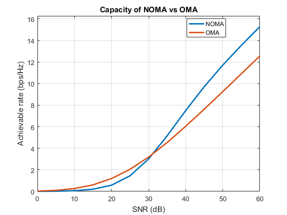
How to simulate BER, capacity and outage probability of NOMA (Rayleigh fading) using MATLAB?
Simulation of BER of Non orthogonal multiple access (NOMA) in Rayleigh fading channel - MATLAB code with explanation
In the previous post, we saw how to simulate a simple two user NOMA network over an AWGN channel in MATLAB. We also plotted the BER vs SNR graphs of both the users and observed the waterfall trend. The AWGN assumption simplified the channel model and allowed us to learn the basic skeletal operation of NOMA. In this post, we will use MATLAB to simulate the capacity, outage and BER performance of a two user NOMA network by following a more realistic model namely, Rayleigh fading model. The MATLAB code to plot BER, capacity and outage probability of NOMA are also available for download in this page. So, let's get started!
Wireless channel is prone to multipath propagation and fading. Several channel models are available to capture the effects of fading. Each model deals with a particular scenario. One such model is Rayleigh fading model. Rayleigh fading model can be used when there is no line of sight (LOS) path between the transmitter and the receiver. In other words, all multipath components have undergone small scale fading effects like reflection, scattering, diffraction, shadowing etc.
We are going to consider an extreme case of Rayleigh fading where each transmitted bit undergoes a different attenuation and phase shift due to multipath transmission. In other words, the channel changes for every bit. We will first look at the system model and signal model of NOMA and then the MATLAB code for simulating it. We will simulate the bit error rate (BER), capacity and outage of NOMA. The MATLAB code for NOMA can be downloaded here.
Capacity and Outage probability for NOMA - MATLAB code
BER of NOMA - MATLAB code
System model
We are considering downlink transmission from base station (BS) to the two users (Can we have more than 2 NOMA users?). Our network will look like this.

User 1 is the far/weak as he is far away from the transmitting BS. User 2 is the near/strong user. Let $d_1$ and $d_2$ denote their distances from the BS.
Signal model
The BS has two distinct messages $x_1$ to user 1 (far user), and $x_2$ to user 2 (near user). $\alpha_1$ and $\alpha_2$ are the power allocation factors for the far and the near user respectively ($\alpha_1$ + $\alpha_2$ = 1). In NOMA, to promote user fairness, more power is given to the far user and less power to the near user. That is, $\alpha_1$ > $\alpha_2$. Throughout this post, we will use $\alpha_1$=0.75 and $\alpha_2$=0.25. This is an arbitrary choice. Let $h_1$ and $h_2$ denote the channel from the BS to the far and the near user respectively.
See this post to find how performance of NOMA varies with different choices of $\alpha_1$ and $\alpha_2$. To see how to optimize $\alpha_1$ and $\alpha_2$, see this post: How to do power allocation in NOMA?
NOMA encoding and transmission
As we know already, the superposition coded NOMA signal transmitted by the BS is, $$x = \sqrt{P}(\sqrt{\alpha_1}x_1 + \sqrt{\alpha_2}x_2)$$ where, $P$ is the transmit power. The copy of $x$ received at the far user after propagating through channel $h_1$ is, $$y_1 = h_1x + w_1$$ Similarly, the copy of $x$ received at the near user after propagating through channel $h_2$ is, $$y_2 = h_2x + w_2$$
NOMA decoding at User 1 (far user)
Expanding the received signal at user 1, \begin{align} y_1 &= h_1x + w_1\\ &= h_1\sqrt{P}(\sqrt{\alpha_1}x_1 + \sqrt{\alpha_2}x_2) + w_1 \\ &= \underbrace{h_1\sqrt{P}\sqrt{\alpha_1}x_1}_\textrm{desired & dominating} + \underbrace{h_1\sqrt{P}\sqrt{\alpha_2}x_2}_\textrm{interference & low power} + \underbrace{w_1}_\textrm{noise} \end{align} Since $\alpha_1$ > $\alpha_2$, direct decoding of $y_1$ would yield $x_1$. The term containing the $x_2$ component will be treated as an interference. The signal to interference and noise ratio for the far user is, $$\gamma_1 = \dfrac{|h_1|^2P\alpha_1}{|h_1|^2P\alpha_2+\sigma^2}$$ and his achievable data rate is, $$R_1 = log_2(1 + \gamma_1) = log_2(1+\dfrac{|h_1|^2P\alpha_1}{|h_1|^2P\alpha_2+\sigma^2})$$
NOMA decoding at User 2 (near user)
Expanding the received signal at user 2, \begin{align} y_2 &= h_2x + w_2\\ &= h_2\sqrt{P}(\sqrt{\alpha_1}x_1 + \sqrt{\alpha_2}x_2) + w_2\\ &= \underbrace{h_2\sqrt{P}\sqrt{\alpha_1}x_1}_\textrm{interference & dominating} + \underbrace{h_2\sqrt{P}\sqrt{\alpha_2}x_2}_\textrm{desired & low power} + \underbrace{w_2}_\textrm{noise} \end{align} User 2 must first perform successive interference cancellation (SIC) before decoding his own signal. SIC is carried out as follows:
- $y_2$ is directly decoded to obtain $x_1$ or rather, an estimate of $x_1$, that is $\tilde{x}_1$.
- $y_2' = y_2 - \sqrt\alpha_1 \tilde{x}_1$ is computed.
- $y_2'$ is decoded to obtain an estimate of $x_2$.
We are making a perfect SIC assumption here. What happens if SIC is imperfect?
The signal to interference and noise ratio at the user 2 for decoding the user 1 signal (before SIC) is, $$\gamma_{1,2} = \dfrac{|h_2|^2P\alpha_1}{|h_2|^2P\alpha_2+\sigma^2}$$ The corresponding achievable data rate is, $$R_{1,2} = log_2(1 + \gamma_{1,2}) = log_2(1+\dfrac{|h_2|^2P\alpha_1}{|h_2|^2P\alpha_2+\sigma^2})$$ After after cancellation of user 1's signal using SIC, the signal to noise ratio at the user 2 for decoding its own signal is, $$\gamma_2 = \dfrac{|h_2|^2P\alpha_2}{\sigma^2}$$ The corresponding achievable data rate is, $$R_2 = log_2(1 + \gamma_2) = log_2(1+\dfrac{|h_2|^2P\alpha_2}{\sigma^2})$$
Here, we have considered only two NOMA users. We can also multiplex more than two users in the same frequency carrier to accommodate more users in our network.
Simulation using MATLAB
Now that we have seen the mathematical details of NOMA we can go ahead and write a MATLAB code to simulate it. We will write two codes. One to study the BER performance and another one to study the capacity and outage performance of NOMA. So, let's get started.
Capacity and outage probability of NOMA - MATLAB simulation
You can download the MATLAB code to plot capacity and outage probability of NOMA here. Capacity and Outage probability for NOMA - MATLAB code- First, let's declare the values of some parameters. Let's say the distances are, $d_1 = 1000$ meters and $d_2 = 500$ meters. Let's set the power allocation factors as $\alpha_1 = 0.75$ and $\alpha_2 = 0.25$. You can set any values for these parameters but make sure that the far user is given the higher fraction of power.
- We want a plot of capacity and outage probability as a function of transmit power. So, let's initialize a range of transmit power from 0 dBm to 40 dBm
- Let's set our system bandwidth as $B = 1MHz$. Let's calculate the thermal noise power as $No = kTB$, where $k = 1.38\times 10^{-23} J/K$,$T=300K$.
- Next, we have to generate the Rayleigh fading coefficients $h_1$ and $h_2$ to simulate the channel between the two users. This can be done using the following MATLAB command $h_i = \sqrt{d_i^{-\eta}}(randn(1,N)+1i*randn(1,N))/\sqrt{2}$. Here, $\eta$ is called the path loss exponent.Typically we set $\eta=4$
- To plot capacity, we need to calculate $R_1 = log_2(1+\dfrac{|h_1|^2P\alpha_1}{|h_1|^2P\alpha_2+\sigma^2})$, $R_{1,2} =log_2(1+\dfrac{|h_2|^2P\alpha_1}{|h_2|^2P\alpha_2+\sigma^2})$, and $R_2 = log_2(1+\dfrac{|h_2|^2P\alpha_2}{\sigma^2})$.
- Find the average value of each of the above quantities for every transmit power
- Calculating the above quantities for different power levels (for eg., from 0 to 40 dBm), we get a plot as shown below:
- Next, we will plot the outage probabilities. Set target rate for each user. For example, for user 1, we set the target rate as 1 bps/Hz and for user 2, we set the target rate as 2 bps/Hz.
- Count the number of times the values calculated in step 5 fall below the target rates and take the average. In other words, set a counter for user 1, which is incremented every time $R_1 \lt 1 bps/Hz$ and another counter for user 2 which increments every time $R_{1,2} \lt 1 bps/Hz$ or $R_2 \lt 2 bps/Hz$
- Plot the outage probabilities as a function of transmit power and the graph would look like this:


BER of NOMA - MATLAB simulation
You can download the MATLAB code to plot BER of NOMA here. BER of NOMA - MATLAB code- Follow steps 1 to 4 of capacity and outage simulation explained above
- Let's next generate noise samples for both users. The formula is, $w_i = \sqrt{noise power}(randn(1,N) + 1i*randn(1,N))/\sqrt{2}$
- Generate random binary data for both users
- Modulate the data using any digital modulation scheme. In the code given here, BPSK is used for both users.
- Calculate the superposition coded signal $x$
- Calculate $y_1$ and $y_2$
- Equalize $y_1$ and $y_2$ by diving by $h_1$ and $h_2$ respectively
- From the equalized version of $y_1$ perform direct BPSK demodulation to get $\tilde{x_1}$.
- Compare $\tilde{x_1}$ with user 1's original data and estimate BER using the biterr function
- Directly decode the equalized version of $y_2$ to estimate $x_1$
- Remodulate $x_1$ and subtract the remodulated $x_1$ component after multiplying it with $\sqrt{\alpha_1}$ from the equalized version of $y_2$. Decode this signal to get $\tilde{x_2}$.
- Compare $\tilde{x_2}$ with user 2's original data and estimate BER using the biterr function.
- Plot the BERs as a function of transmit power and the graph would look like this:

Note
Make sure you use the linear value of power in all calculation and not the dBm value. (Especially while calculating $R_1$, $R_{1,2}$, $R_{2}$. Next post: How to do power allocation in NOMA?References:
- Theoretical BER: F. Kara, H. Kaya, BER Performances of Downlink and Uplink NOMA in the Presence of SIC Errors over Fading Channels. IET Communications. Vol. 12, no. 15, pp. 1834-1844.
- Y. Saito, Y. Kishiyama, A. Benjebbour, T. Nakamura, A. Li, and K. Higuchi, Non-Orthogonal Multiple Access (NOMA) for Cellular Future Radio Access, IEEE 77th Vehicular Technology Conference (VTC Spring) (Dresden, Germany), 2013, pp. 1–5.
- A. Benjebbour, Y. Saito, Y. Kishiyama, A. Li, T. Harada, and T. Nakamura, Concept and Practical Considerations of NonOrthogonal Multiple Access (NOMA) for Future Radio Access, International Symposium on Intelligent Signal Processing andbCommunication Systems (ICPACS 2013) (Okinawa, Japan), 2013, pp. 770– 774.

Shouldn't we plot it with respect to the thing called Eb/No or something ? I am not sure why most BER curve plot with that kind of thing ?
ReplyDeleteYes. We can plot them as a function of Eb/No or as a function of SNR also.
DeleteOh in that case then how can we determine the mean and the variance of the noise to achieve the desirable Eb/N0 ?
DeleteThere is this relation between SNR and Eb/No. For a given Eb/No, the SNR would be,
DeleteSNR = (Eb/No)*bit rate/BW
where the bit rate (in bps) and bandwidth (in Hz) depends on the modulation scheme.
To achieve the desirable Eb/No, we can use this expression to obtain the variance of AWGN as P/SNR, where P is the measured signal power and SNR depends on Eb/No.
Again, the mean would be zero.
Hi Joe,
DeleteI am still having some difficulties plotting the BER vs Eb/No plot. How do i get Eb/No from the transmit power given in the code and plot it?
Thanks
Hi Joel, from the transmit power and noise power, you can find the transmit SNR. Once the SNR is known, Eb/No can be calculated as SNR*Bandwidth/bitrate
DeleteHi, i want to ask in the 2 user noma system, what's the bit rate if using bpsk? For the common bpsk, there should be only one bit/symbol but in norma there more than one signal transmitted together, will it change?
DeleteHi, Do you have the matlab code for the comparison of capacity of FDMA and noma?
DeleteHi, i am conffused about why the noise power is -174+10*log10(BW) what is the number -174?
DeleteHi, thermal noise power = kTB, where k is boltzmann constant, T is temperature (300K).
Delete10log(kT/10^-3) = -174 dBm
Hi ,
DeleteStill , I am confused of finding SNR from transmit power in Rayleigh fading ?
Hi Sakthik, just fix the noise power to be some value (for eg., -174 dBm) and
Deletecalculate SNR = Pt - No, where Pt is the transmit power in dBm
I think SNR= Pt/No
DeletePlease correct me
Hi San, in linear scale snr = Pt/no. In dB scale, it is SNR = Pt - No.
DeleteExcellent tutorial on NOMA simulation! The step-by-step breakdown of BER, capacity and outage probability makes this one of the clearest practical guides available for NOMA researchers.
DeleteOne thing worth highlighting for anyone going deeper into NOMA security — the outage probability framework you have described here extends naturally into Physical Layer Security analysis. When you add an eavesdropper to the NOMA system, the outage probability becomes the Secrecy Outage Probability — the probability that the secrecy capacity falls below a target rate. The Rayleigh fading model you used here is the same foundation for PLS analysis, and your SINR expressions map directly to secrecy capacity expressions once the eavesdropper channel is included.
For anyone interested in how NOMA connects to Physical Layer Security with probabilistic models, Python implementations, and secrecy metrics including SOP and average secrecy rate:
Probabilistic Models for Physical Layer Security
How did you get the theoretical BER ? What is the closed form expression ?
ReplyDeleteHi! Closed form expression for BER was derived by following the steps given in this paper as reference:
DeleteKara, Ferdi & Kaya, Hakan. (2018). BER Performances of Downlink and Uplink NOMA in the Presence of SIC Errors over Fading Channels. IET Communications. 12. 1834-1844. 10.1049/iet-com.2018.5278.
You can refer this work for details
Can you explain why user 1 has less achievable capacity rate than user 2?Like why the graph behaves like this?
ReplyDeleteUser 1 has limited achievable capacity because of the interference from user 2. User 2 does not have this problem because interference is removed by SIC. If we see the expressions for their achievable rates, R1 has an additional interference term at the denominator, while R2 does not have this term.
DeleteCan you provide the code for simulation of OFDM ber vs snr ?
ReplyDeleteHi! I have the code for ofdm. Ping me electronicswithme@gmail.com and i will send it to you.
DeleteHELLO can you please help me i am trying to create the same code but in QPSK not BPSK and with Rayleigh distribution
ReplyDeletei need help to write the same code with QPSK modulation + AWGN (0 main and unit variance) + Rayleigh distribution with 0 main and (SEGMA^2 ) variance but (BER vs SNR). i have little problems please help me .
ReplyDeleteHi Rania! You can use the same code given in this post. Just change the modulation and demodulation parts.
DeleteIf your problem still persists, can I know where exactly you get the error?
This comment has been removed by the author.
ReplyDeleteHi Trishna,
DeleteI read through your code and made some changes in the demodulation part.
You can download the modified code from this link
https://drive.google.com/file/d/1YFnkQJeQkyB5xSJn5W8GmLzcPb4WcLeC/view?usp=sharing
hope this helps
Thanks a lot. I understood the concept so well and also to model it. Can't thank you enough for your generosity. Thanks Thanks Thanks! Many Thanks!
DeleteCan you please tell how to simulate for rician channel. Ive been trying to find a matlab code to make it work and unfortunately I am unable to do so. Please help
ReplyDeleteHi Ankita, Rician channel is very similar to Rayleigh fading channel, except for the presence of LOS path
DeleteUsually we model Rayleigh fading coefficients as h = x + i*y, where, x and y are zero mean, gaussian random variables.
In the case of Ricean fading also, we model h as, h = x + i*y. But now, x is non-zero mean gaussian random variable while y has zero mean. Both x and y have the same variance.
The Ricean parameter (K) can be used to calculate the mean of x and the variance of both x and y.
Here is a sample code for NOMA in a ricean fading channel
https://drive.google.com/file/d/1YFnkQJeQkyB5xSJn5W8GmLzcPb4WcLeC/view?usp=sharing
Hope this helps
@Joe what does this equation for Rayleigh fading indicate???
ReplyDeletezs1=complex(randn(2,1),randn(2,1))/sqrt(2);
what is 2, 1 here???
Hi Satarupa,
Deleterandn(2,1) generates zero mean, unit variance gaussian random variables in the form of a 2 x 1 vector.
complex(randn(2,1),randn(2,1)) would give the rayleigh fading coefficients (2x1 vector) in the form of x + iy, where x and y are independent gaussian random variables with zero mean unit variance.
Since the variance of randn(2,1) is 1, complex(randn(2,1),randn(2,1)) will have variance 2. So we divide by sqrt(2) to make the overall variance to be 1.
Hope this helps
Yes, ThankYou...
DeleteHi Joe,
ReplyDeleteCan you explain to me why BPSK modulation has this formula?
x1 = 2*data1 - 1;
x2 = 2*data2 - 1;
What about QPSK modulation?
And
x1_hat(eq1>0) = 1;
x12_hat(eq2<0) = -1;
x2_hat(real(y2_dash)>0) = 1;
what does this all mean?
Please help me!
Hi, in the formula
Deletex = 2*data - 1,
If you sustitute data = 0, you will get x = -1, and if data = 1, you will get x = 1. Thus we have mapped bit 0s to -1s and bit 1s to +1s, which is BPSK modulation
QPSK is just BPSK done both in I and Q channels.
x1_hat(eq1>0)=1
This command assigns a value of 1 to x1_hat whenever eq1 (the received symbol to be demodulated) is greater than 0. Otherwise, x1_hat will be set to 0. This line performs BPSK demodulation, i.e., symbol to bit mapping
Thank you for your help!
Deletex12_hat(eq2<0) = -1;
Deleteshouldn't it be x12_hat(eq2<0) = 0;
y2_dash = eq2 - sqrt(a1*pt(u))*x12_hat; what is the use of this command?
Can you give me permission to use your matlab code in my report? do you mind about that?
ReplyDeletehi....can you please check the code for last figure of theoretical and simulation BER. In the code theoretical BER calculation part is not there
ReplyDeleteHi, thanks for notifying. Updated it!
Delete
ReplyDeleteI'm sorry I might have to ask a very stupid question. What's the difference between the path loss exponent used here to calculate the channel factor and the path loss (dB) calculate by Free Space loss? What's the unit of path loss exponent here?
We know that the path loss is proportional to (distance)^(path loss exponent).
DeleteThe path loss exponent is just a number in the range 2 to 6.
It gives the rate at which the signal power decays with distance.
In free space model, the path loss exponent = 2.
To model more dense urban environments, we have chosen the exponent to be 4.
Hi!
ReplyDeleteWhy when calculating the signal to noise ratio, the channel gain is squared?
and
I really don't understand what this formula means
R_1=〖log〗_2 (1+γ_1 )=〖log〗_2 (1+(|h_1 |^2 Pα_1)/(|h_1 |^2 Pα_2+σ^2 ))
Please helps!
The definition of SNR is signal power/noise power. The rayleigh fading coefficient, h is in the voltage amplitude domain.
DeleteBut in SNR equation, we have to represent it in terms of its power. We know that power = voltage^2/R. Assuming R = 1 ohm, power of the rayleigh fading coefficient is |h|^2
The formula for R1 is a standard formula for achievable rate of a wireless channel. In general, for any wireless channel with snr = gamma, the achievable rate is given by log_2(1+gamma). This is Shannon's capacity equation.
Thank for your help!
DeleteHi Joe,
ReplyDeleteWhy do we have to calculate the average value of R1,R12,R2 ?
and
p1 = zeros(1,length(Pt)); Tại sao bạn sử dụng hàm số không?
Can you explain what 'pout' here means?
pout1=p1/N
Thank you!
Hi, since the wireless channel is very dynamic, the instantaneous capacities will fluctuate so much. Averaging them would give us more useful insights about the overall channel behavior.
DeletePout is the outage probability. p1 counts the number of times the achievable rate falls below the target rate, out of N transmissions.
Hi joe
ReplyDeleteThank you for this effort
May I know what we are modeling from line 68 to line 87?
Another question is can I get some notes about the resulting BER scheme?
Hi, we are calculating the theoretical BER in those lines.
DeleteFor more details on theoretical BER derivation, please refer this paper:
Kara, Ferdi & Kaya, Hakan. (2018). BER Performances of Downlink and Uplink NOMA in the Presence of SIC Errors over Fading Channels. IET Communications. 12. 1834-1844. 10.1049/iet-com.2018.5278.
OK
DeleteThank you
What about modeling the Matlab program from line 68 to line 87?
gam_a = 2*((sqrt(a1*pt(u))-sqrt(a2*pt(u)))^2)*mean(g1)/no;
Deletegam_b = 2*((sqrt(a1*pt(u))+sqrt(a2*pt(u)))^2)*mean(g1)/no;
ber_th1(u) = 0.25*(2 - sqrt(gam_a/(2+gam_a)) - sqrt(gam_b/(2+gam_b)));
gam_c = 2*a2*pt(u)*mean(g2)/no;
gam_d = 2*((sqrt(a2) + sqrt(a1))^2)*pt(u)*mean(g2)/no;
gam_e = 2*((sqrt(a2) + 2*sqrt(a1))^2)*pt(u)*mean(g2)/no;
gam_f = 2*((-sqrt(a2) + sqrt(a1))^2)*pt(u)*mean(g2)/no;
gam_g = 2*((-sqrt(a2) + 2*sqrt(a1))^2)*pt(u)*mean(g2)/no;
gc = (1 - sqrt(gam_c/(2+gam_c)));
gd = (1-sqrt(gam_d/(2+gam_d)));
ge = (1-sqrt(gam_e/(2+gam_e)));
gf = (1-sqrt(gam_f/(2+gam_f)));
gg = (1-sqrt(gam_g/(2+gam_g)));
ber_th2(u) = 0.5*gc - 0.25*gd + 0.25*(ge+gf-gg);
gamma1(u) = a1*pt(u)*mean(g1)/(a2*pt(u)*mean(g1) + no);
gamma2(u) = a2*pt(u)*mean(g2)/no;
These lines of code for programming what?
Lines 68 to 87 are modelling the closed form expression of theoretical BER
DeleteHi Joe,
DeleteCan you please explain why OP of user 1 is less than user 2? Is it because of power allocation?
Hi Trishna,
DeleteIt's because of the interference. User 1 performs direct decoding by treating the user 2 data as interference. (as can be observed in the denominator of R1 expression)
User 2 does not experience any interference since it is removed by SIC
Hi Joe,
DeleteHow did you go about to calculate the theoretical BER? could you just provide a quick over view of line 68 to 87.
Thanks
Hi Joel,
DeleteThe procedure for derivation of closed form expression is explained in this paper:
Kara, Ferdi & Kaya, Hakan. (2018). BER Performances of Downlink and Uplink NOMA in the Presence of SIC Errors over Fading Channels. IET Communications. 12. 1834-1844. 10.1049/iet-com.2018.5278.
Hi Joe,
ReplyDeleteWhy do you set the target rate for user 1 to 1bps/hz and user 2 to 2bps/hz ?
Hi, it is up to us to set the target rates. We set them according to the user's QoS requirements. Usually we set a higher target rate to the near user because he has the better channel
DeleteHi,
DeleteLet me ask what does R12 mean here? Why must it?
Thank you!
Hi, user 2 must first decode x1, then perform SIC, then decode his own x2.
DeleteR12 is the achievable rate at user 2 to decode x1.
R12 is also an important parameter because, if R12 is less than user 1's target rate, it is possible that user 2 decodes x1 erroneously. This would lead to SIC error propagation, leading to errors in decoding of user 2's own signal
Hello!
DeleteIn the calculation formula R1, R2, the value of the variance is not added, but instead we calculate the thermal noise power in the matlab code? Please explain more about this!
Thank you!
Hi, in R1 and R2, the sigma^2 represents the noise variance. Noise power (kTB) is equal to its variance.
DeleteHi joe,
DeleteLet me ask why is the bit error rate and outage probability of the remote user always higher than the near user despite being allocated more power?
Thank you!
Hi, although the remote user is allocated more power, he still suffers interference due to near user transmission. As a result, he has high BER and outage.
DeleteHello! How can I convert the channel gain h into dB?
ReplyDeleteHi, 10log(channel gain) will give the value in dB
DeleteHi Joe, in your code you have used noise level as -174. Can we change this value or it should be fixed?
ReplyDeleteHi, -174 dBm is the fixed value of thermal noise power in 1 Hz bandwidth, when the temperature is 300K.
Delete10log(kT/10^-3) = -174 dBm, where k is boltzmann constant and T is the temperature.
hello Joe, i would like to have your help. i am working on cooperative NOMA for 2 users with direct link, do you have MATLAB code for it.
DeleteHi, I need sample code on NOMA D2D please
ReplyDeletethanks
Hi, we will see about that in a future post!
Deletehi Joe
ReplyDeleteIf we want to implement the raised cosine transmitter and receiver filters on both sides then how are we going to equalize the Y1 And Y2.
Sorry for this very dumb question!!!!!
hello JOE can you answer me please ?
ReplyDeleteNOMA exist from 2013 why we just use it for the 5G only why we didn't use it before ?
what i am trying to say is why NOMA is only used for 5G only ?
Hi Rania, unlike the old times, these days, the computaional processing capacity of hardware can support NOMA signal processing. This is one of the main reasons for the push towards NOMA now.
DeleteThis comment has been removed by the author.
DeleteDear Researchers,
ReplyDeleteI found this block is very effective and helpful.
I need sample code for OFDM based NOMA.
Thanks in advance.
Hi Nayan, glad to know you found the posts useful. More articles about OFDM based NOMA will be posted soon! Thank you
DeleteHello Joe
ReplyDeleteI found your blog on NOMA too useful, simple with good quality and clarity. I need code of cooperative SWIPT NOMA, please forward it.
regards
Hello Joe ... I need the MATLAB codes to simulate the massive MIMO-NOMA ... Help me please. Thank you
ReplyDeleteHi, right now I don't have the code for MIMO-NOMA. But we will see about MIMO-NOMA in future posts..
DeleteHi,do you have code about adding imperfect channel state information into NOMA system ?
ReplyDeleteHi Thomas, ping me electronicswithme@gmail.com and I will send it to you
DeleteHey joe, i have some some code for NOMA in which i have only transmitter side, no modulation ... actually i want some BER vs SINR graphs for my work.
ReplyDeleteWill you please update my code as i am beginner in NOMA and trying to understand things but i am stuck in it.
i sent code on electronicswithme@gmail.com please have a look on it .
OK, I will take a look at it and let you know
Deletewhy we use equation of bpsk is 2*k-1 ??
ReplyDeleteHi, BPSK maps bits 0 & 1 as +- 1.
DeleteThe expression s = 2*k-1 also does the same thing. It maps bit k=0 to symbol s = -1 and bit k=1 to symbol s = +1.
However, this is not the only way to do this. We can also use if---else conditional statement to perform this mapping.
Hello sir,
ReplyDeleteYour posts are very helpful.
How to plot BER vs SNR? Can u provide the code for that?
Hi surya,
DeleteBER vs SNR codes for AWGN channel are available in this post:
https://ecewireless.blogspot.com/2020/04/simulation-of-ber-of-non-orthogonal.html
Hope this helps
In this post do you have considered BPSK modulation at both users?
ReplyDeleteHi Umer, yes, BPSK is used for both users here. But it is also possible to go for different modulation schemes to the users
DeleteHi Dr joe
ReplyDeleteCan you please give me refrences used for understand OP?
thank you for your time
best regrades
Hi, please go through the papers given in the reference section.
DeleteHope this helps
Hi Joe ,Could you please send MATLAB Code for NOMA with imperfect CSI.
ReplyDeletesreenu.sunkaraboina@gmail.com
Hi Sunkaraboina, yet to write the code. Will send it soon!
DeleteCan you explain how probability of error is calculated from the constellation of the first reference paper?
ReplyDeleteHi Umer, the first reference paper is a very good foundational work on NOMA theory & understanding it would widen our NOMA toolbox. It would be great to make a post on the theoretical derivation of NOMA BER. We'll cover that in a future post
Deletewhy result of near is the best ( in the NOMA big power go to the far user then far user must get best result )
ReplyDeletei don't understand
Hi Abdelrahim, the results depend on several parameters like distance, target rates etc., in addition to power allocation. One explanation for this behavior would be: although the far user is allocated higher power, he suffers from interference due to the near user's data. The near user does not have this interference problem because he performs SIC. Hence, the near user has better performance than the far user. Hope this helps.
Deletethanks alooooot bro
Deletebut i need to know , The far user decode only his signal but the near user use SIC so he is decode the signal of the far user and his signal so the error probability is big
That is what i know always near user have small power and must do 2 decode so have big BER and bad spectral efficiency and every thing is bad ^_^ is that right ? or what i must understand
thanks bro for reply quickly you are is the best
Hi Abdelrahim, the near user has a good channel with the Base station, while the far user does not. So, the near user can decode the far user's signal accurately and also do SIC.
DeleteDear Dr. Joe,
ReplyDeletePlease guide how to perform equalization in uplink NOMA. Kindly upload code for UL NOMA.
Hi, thanks for the suggestion. Will make a post about uplink NOMA soon
DeleteI am looking for a code to compare OMA NOMA outage probability and BER
DeleteCan anyone post the matlab code for outage probablity of MIMO-NOMA and OMA??
ReplyDeleteHi, outage of MIMO-NOMA and OMA is covered in this post
Deletehttps://ecewireless.blogspot.com/2020/11/mimo-noma.html
Hope this helps!
dear joe, can you provide the codes on ergodic secrecy rate of multicell MIMO-NOMA?
Deletehave help in coding part of outage probability of MIMO-NOMA?
DeleteHi there Joe :) I really love all the work that you have put in. Could you kindly check your email regarding the inquiry of OFDM - NOMA codes?
ReplyDeleteThank youu so much!
Regards
Sure!
DeleteHi Joe, thank you for this useful post. Please I want the code of OFDM-NOMA
DeleteThank you very much
Hi,Dr
ReplyDeletei check references for OP but i don't found it if you can share with me the article you used to make condition in matlab code i will be thankful
Hi, you can follow the steps given in reference 1 to derive expressions for this system
Deletethank you
DeleteHello Everyone,
ReplyDeletecould anyone provide some information on "Outage Probablity" and how it performs ?
Hi, the received signal must be strong enough to be sensed and reliably decoded by the receiver. When it is not strong enough, we say that the receiver is in outage. We find the outage probability by counting the number of times the received power (or rate) falls below a predefined threshold.
DeleteHope this helps
Hi Joe, please could you give us a simple code about to to find the outage probability in religh fading channel when the SINR < SINR_ threshold please please
Deletehi joe; can you tell me, how can I superpose the signals of two users, the first one is encoded by QPSK, and the second one BPSK because mod1 and mod2 have not the same dimension.
ReplyDeleteHi, if you generate N bits for the BPSK user, then generate 2N bits for the QPSK user. After performing the respective modulations, both users will have N symbols. Next you can perform superposition coding of symbols as before. (Because QPSK offers twice the rate as BPSK)
DeleteHope this helps
thank you very match Joe;
Deletecan I set N/2 for BPSK and N for QPSK.
can you verify to me this code
problem BER of user1 is very high
clc; clear variables; close all;
N = 10^5; %Number of simulations
SNR = 0:30; %SNR range in dB
snr = db2pow(SNR); %SNR range in linear scale
Modulator1=comm.QPSKModulator('BitInput',true);
Demodulator1=comm.QPSKDemodulator('BitOutput',true);
Modulator2=comm.BPSKModulator('PhaseOffset',0);
Demodulator2=comm.BPSKDemodulator('PhaseOffset',0);
%Generate random data bits for transmission
s1 = randi([0 1],N,1); %Data bits of user 1
s2 = randi([0 1],N/2,1); %Data bits of user 2
% QPSK modulation of data
xmod1 = step(Modulator1,s1);
xmod2 = step(Modulator2,s2);
% Set power factor for users
a1=[0.2 0.3] ;a2= 1-a1 ;
% superposition coding
x = sqrt(a1).*xmod1 + sqrt(a2).*xmod2;
% Add AWGN to x (Transmit x through an AWGN channel)
for u = 1:length(snr)
y1 = awgn(x,SNR(u),'measured'); %Received signal at user 1 corrupted by AWGN
y2 = awgn(x,SNR(u),'measured'); %Received signal at user 2 corrupted by AWGN
%AT USER 2
%Direct decoding of x from y2
x2_hat1=step(Demodulator2,y2(:,1)); %just a buffer
x2_hat2=step(Demodulator2,y2(:,2)); %just a buffer
%AT USER 1
%Direct decoding of x from y1
x12_est1 = step(Demodulator1,y1(:,1)); %just a buffer
x12_est2 = step(Demodulator1,y1(:,2));
x12_remod1 = step(Modulator1, x12_est1);
x12_remod2 = step(Modulator1, x12_est2);
%Subtract remodulated x12_est component from y1
rem1 = y1(:,1) - sqrt(a2(1,1)).*x12_remod1;
rem2 = y1(:,2) - sqrt(a2(1,2)).*x12_remod2;
%Decode x1 from rem
x1_hat1 = step (Demodulator1,rem1);
x1_hat2 = step (Demodulator1,rem2);
%Estimate BER
ber1(u) = biterr(s1,x1_hat1)/N;
ber2(u) = biterr(s2,x2_hat1)/(N/2);
ber3(u) = biterr(s1,x1_hat2)/N;
ber4(u) = biterr(s2,x2_hat2)/(N/2);
end
%plot BER curves
f1=figure(1);
semilogy(SNR, ber1,'k-*',SNR, ber2,'b-s',SNR, ber3,'r--^',SNR, ber4,'g--^' ,'linewidth', 1.5);
legend('User 1 \alpha_1 = 0.2','User 2 \alpha_2 = 0.8','User 1 \alpha_1 = 0.3','User 2 \alpha_2 = 0.7','Location','northwest');
axis([0 30 10^-4 1]);
xlabel('SNR (dB)');
ylabel('BER');
grid on;
title('BER for NOMA three users in AWGN channel');
Is this the code for BER vs SNR
DeleteI want to simulate BER NOMA under nyusim channel we can consider Path loss of nyusim channel as h channel gain in Rayleigh fading channel
ReplyDeleteHi abdelbasset, I am not familiar with NYUSIM. So I've no idea about it.
DeleteI request any our blog followers working on NYUSIM to hop in and respond to this thread.
hi joe,can u some new algoirthms for power allocation and user scheduling in NOMA?
ReplyDeleteHi, we'll see more about power allocation and user pairing strategies in future posts
Deletehi joe , how can I simulate NOMA under NYUSIM CHANNEL?
ReplyDeletewe can consider nyusim channel gain as path loss of the channel .
Hi abdelbasset, I am not familiar with NYUSIM. So I've no idea about it.
DeleteI request any our blog followers working on NYUSIM to hop in and respond to this thread.
In term of outage probability, will the outage probability for each OMA user ALWAYS better than the outage probability of each NOMA user right ?
ReplyDeleteParticularly
Outage Probability of Near User OMA < Outage Probability of Near User NOMA
Outage Probability of Far User OMA < Outage Probability of Far User NOMA
I have that feeling but do not know how to confirm that, it seem that NOMA user experience some sort of intra resource block interference
Hi Minh, if we look at the rate equations of OMA and NOMA,
DeleteR_oma = (1/N)*log2(1+snr)
R_noma = log2(1+sinr)
Due to the presence of the (1/N) factor, OMA users experience reduced achievable rate, and hence more outage.
Especially, the near NOMA user always experiences less outage than near OMA user.
But this may not always be true for the far users (because they suffer from interference, as you mentioned). For the far user, other factors like power allocation, channel conditions must also be considered.
Hi joe , how can i create MATLAB code, when two users are allocated two different distances from BS?
ReplyDeleteHi, You can just modify the distances in the code provided in this post itself
DeleteHey
ReplyDeleteI have tried to implement BER vs SNR with the help of your code for fair power allocation system. I am facing some errors in the same. I have mailed my queries to you. Could you please check them?
Hi Parva, I made some corrections in your code. It is working now.
DeleteMailed it to you.
How do we extend the SIC for more than 2 users?
ReplyDeleteHi, SIC for more than two users is explained in this post:
Deletehttps://ecewireless.blogspot.com/2020/06/ber-of-3-user-non-orthogonal-multiple.html
For BER vs SNR curve, I am taking SNR=received power/ Noise power. But now the performance of users got reversed, far user is performing better than near user. Is it correct? Can I send my file to you for checking it ?
ReplyDeleteOK, i'll take a look at it
DeleteCan you please send me your email id?
Deleteelectronicswithme@gmail.com
DeleteCan you send the code matlab for me too plz
DeleteAbdelrahimjomaa2@gmail.com
send me the code pleaseeeeeeeee
DeleteHi Joe. I am thinking about the effect of channel equalizer on BER. I checked the paper [1] (BER theoretical), it seems that the model of [1] did not consider equalizer and the result was based on demodulating the raw received signal (un-equalized). However, it seems the equalizer is essential. If possible, could you please advise some insights on this question? Best.
ReplyDeleteHi joe,
ReplyDeletefrom where you have taken free space path loss calculations? any reference? pls provide
Hello Everyone...
ReplyDeleteCan anyone Please send me the Matlab codes of OUTAGE PROBABLITY of MIMO-NOMA or NOMA in Rician or AWGN fading channels??
Dear Joe,
ReplyDeleteThanks for your quality posts about NOMA. Can you create blogs about NOMA (5G) interference with IRS (6G)? I am extremely looking forward to your new blogs on this subject.
Best regards
Hi Joe, great post! Learned a lot. Could you please inform me how do I calculate the Theoretical Outage Probabilities for the far and near users , and then plot with the Analytical Outage Probabilities? The final graph would be on X axis: Transmit Power (in dBm) and on the Yaxis, Theoretical and Analytical Outage Probabilities.
ReplyDeleteYou have shown this for the BER vs Transmit Power (in dBm). Could you please also do the same for Outage Probabilities vs Transmit Power (in dBm)?
Thanks a lot for your help!
Hello, you have source code matlab for this general? I need it, you can sent to me by mail: thienthanhaovai@gmail.com
ReplyDeletethank you!
Hello Joe
ReplyDeleteFor decoding x1 from y2 you have mentioned the given code:
-------------------------------------------------------------------------------------------
%AT USER 2-------------------------
%Direct decoding of x1 from y2
1. x12_hat = ones(1,N);
2. x12_hat(eq2<0) = -1;
3. y2_dash = eq2 - sqrt(a1*pt(u))*x12_hat;
4. x2_hat = zeros(1,N);
5. x2_hat(real(y2_dash)>0) = 1;
---------------------------------------------------
why have you used line 2: x12_hat(eq2<0) = -1; shouldn't it be x12_hat(eq2<0) = 0
Also explain the use of : y2_dash = eq2 - sqrt(a1*pt(u))*x12_hat;
Hi Huma,
Deletey2_dash = eq2 - sqrt(a1*pt(u))*x12_hat;
This command performs the successive interference cancellation. Please see this post for more details:
https://ecewireless.blogspot.com/2020/04/noma-graphical-example-of-successive.html
I hope that post will answer why x12_hat(eq2<0) = -1 was used directly instead of x12_hat(eq2<0) = 0
Thankyou.
DeleteDear Joe,
ReplyDeleteThanks for your quality posts about NOMA, do you have any matlab code for NOMA with physical layer security.
best regards,
Hey Hi, have you got the code for NOMA with Physical layer security? pls share with me. poovarasivakumar@gmail.com
DeleteMay you please provide the code of Noma for three users using QAM Modulation with AWGN Channel not by Rayleigh fading channel. Secondly how can we map the same code(QAM & QPSK for Three Users using AWGN ) on VLC
ReplyDeleteDear Joe , its a very informative post for NOMA BER analysis in down link scenario, can you post the code for up link scenario
ReplyDeleteHello Everyone can anyone upload mix Modulation Scheme with BPSK QPSK AND 16 QAM NOMA Matlab Code.
ReplyDeleteHii Joe, thank you so much for NOMA matlab codes and for your explanation.
ReplyDeleteplz upload NOMA based Spatial Modulation Matlab code..
thank you!
plz , do you have NOMA based Matlab code? you be very helpful if you shared it with me (m_bairakdar@yahoo.com)
DeleteHiJoe thank you for NOMA Matlab codes can you explain hybrid beaformning with some codes
ReplyDeletethanks a lot
ReplyDeleteHi Joe thank you for NOMA Matlab codes can you explain hybrid beaformning with some codes
ReplyDeletecan u please tell the conclusion for above matlab project
ReplyDeleteThank you Joe for explain hybrid beamforming with some codes
ReplyDeleteDear Joe, please kindly reach out to me at chekwas@engineer.com I have some research works to discuss with you. Thank you.
ReplyDeleteHello Joe, I want to ask a questions. If the user 1 is far from BS and the type of user is D2D pair, how to calculate the SINR? It's that still using h1 with d1 is distance from BS to user 1 or how?
ReplyDeleteVery great and helpful post..
ReplyDeleteYou really deserve appreciation..
I have a question:
(R12(k) < rate1)||(R2(k) < rate2)
For checking outage of user 2, why do we need count also R12?
In other words, in case R2 > rate2 but R12 < rate1, why do you consider this case as an outage for user 2??
Hi joe if alpha1= 0.9 and alpha2=0.1 where I am supposed to modify code of ABER at what expressions can you please highlight the line numbers?
ReplyDeleteMerci Dr. Joe Comment parler de la securité au niveau du recepteur SIC ? Car lors du decodage, l'utilisateur 2 peut avoir les informations sur le message de l'utilisateur 1
ReplyDeleteHi Joe, thank you for the valuable information. Can you please help me with the similar code for RSMA
ReplyDeleteThanks Dr. Joe How about security at the SIC receiver level? Because during the decoding, user 2 can have the information about the message of user 1
ReplyDeleteHello Joe! You 've done a greate job in this blog. Please answer me to that, in order to use this model in THz band communications, is it enough to change the bandwith to BW=10^12 and decrease the distance between the users and the BSs (ex. d1=100, d2=50), or should i do more than that? Thank you in advance!
ReplyDeletehello,help me please ; i want the MATLAB code to plot capacity, outage probability And ber of NOMA as a function of SNR .
ReplyDeleteHi Tar, have you solved it?
DeleteThis comment has been removed by the author.
ReplyDeleteHi sir, can you help me to modify our code (MIMO-NOMA) by using any of the channel coding Turbo or polar
ReplyDeleteHi sir can you help me to optimize the channel using a specific kind of channel coding
ReplyDeleteHello I need Matlab code to plot graph of Outage Probability vs SNR in Raleigh fading channel
ReplyDeleteHello, Can you help me change the modulation to 16 qam, I don't know which point to change to get a low ber. i have change it to 4 Qam successfully, but when trying for 16 qam it doesn't work. i have matlab R2015a.Thank you.
ReplyDeleteHello, i have created the code with configuration 4 qam, but I can't get the correct result with 16 qam format. can someone help me?
ReplyDelete