MIMO - NOMA
System model
Consider a 2 x 1 downlink MIMO system as shown in Fig. 1. Let $d_1$ and $d_2$ denote the distances of U1 and U2 respectively from the MIMO transmitter. Here, we assume $d_1 \gt d_2$. That is, U1 is the weak user and U2 is the strong user.We know that MIMO can be used for either spatial multiplexing (increase achievable rate) or diversity gain (decrease BER). Here, we are using MIMO for achieving diversity gain. Hence, both the transmit antennas 1 and 2 transmit the same information.
Let $x_1$ and $x_2$ denote the information intended for U1 and U2. Following the notation conventions of MIMO, let $h_{rt}$ denote the Rayleigh fading channel between the $t^{th}$ transmit antenna and $r^{th}$ receiver.

It is very clear that MIMO-NOMA provides greater sum rate than MIMO-OMA, due to the fact that both users are served simultaneously with the same frequency resource.


Fig. 1: MIMO-NOMA system model
Signal model
Transmit signal
Signal transmitted by both the transmit antennas are given by, $$x = \sqrt{P}\left(\sqrt{\alpha_1}x_1+\sqrt{\alpha_2}x_2 \right)$$
(1)
where $\alpha_1$ and $\alpha_2$ are the NOMA power allocation coefficients. Since U1 is the weak user, we have $\alpha_1 \gt \alpha_2$.
Received signals
$x$ is transmitted simultaneously by both the transmit antennas. Therefore, the received signal at U1 is,
$$y_1 = xh_{11}+xh_{12}+n_1=x\left(h_{11}+h_{12}\right)+n_1$$
(2)
Similarly, the signal received by U2 is given by,
$$y_2=xh_{21}+xh_{22}+n_2=x\left(h_{21}+h_{22}\right)+n_2$$
(3)
Here, $n_1$ and $n_2$ are AWGN noise samples with mean zero and variance $\sigma^2$
Decoding at user 1
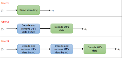
Now, U1 has to decode $x_1$ from $y_1$. Since U1 is the weak user, his signal, $x_1$ is allocated more power. That is, $\alpha_1 \gt \alpha_2$. Therefore, he can directly decode $x_1$ from $y_1$, treating the $x_2$ term as interference.
Substituting for $x$ in (2), we get, $$y_1 = \sqrt{P}\left(\sqrt{\alpha_1}x_1+\sqrt{\alpha_2}x_2\right)\left(h_{11}+h_{12}\right)+n_1$$
(4)
Expanding, $$y_1 = \underbrace{\sqrt{P}\sqrt{\alpha_1}x_1\left(h_{11}+h_{12}\right)}_\textrm{desired}+\underbrace{\sqrt{P}\sqrt{\alpha_2}x_2\left(h_{11}+h_{12}\right)}_\textrm{interference}+n_1$$
(5)
Now, we can write the SINR equation for U1 in decoding $x_1$ as follows,
$$\gamma_1 = \dfrac{P\alpha_1|h_{11}+h_{12}|^2}{P\alpha_2|h_{11}+h_{12}|^2+\sigma^2}$$
(6)
Therefore, the achievable rate at U1 is given by,
$$R_1 = log_2\left(1+\gamma_1 \right)$$
(7)
Decoding at user 2
U2 must decode $x_2$ from $y_2$. Since U2 is the strong user, his signal, $x_2$ is allocated less power. Therefore, in $y_2$, the power of the $x_1$ term will be dominating. So, U2 will first perform direct decoding on $y_2$ to obtain $x_1$. Then successive interference cancellation (SIC) is carried out to remove $x_1$. Then, $x_2$ is decoded.
Substituting for $x$ in (3) and expanding, we get,
$$y_2 = \underbrace{\sqrt{P}\sqrt{\alpha_1}x_1\left(h_{21}+h_{22}\right)}_\textrm{undesired & dominating}+\underbrace{\sqrt{P}\sqrt{\alpha_2}x_2\left(h_{21}+h_{22}\right)}_\textrm{desired}+n_2$$
(8)
The SINR at U1 for direct decoding of $x_1$ is,
$$\gamma_{12} = \dfrac{P\alpha_1|h_{21}+h_{22}|^2}{P\alpha_2|h_{21}+h_{22}|^2+\sigma^2}$$
(9)
After SIC, the first term of (8) will be removed and the remaining signal will be,
$$y'_2 = \underbrace{\sqrt{P}\sqrt{\alpha_2}x_2\left(h_{21}+h_{22}\right)}_\textrm{desired}+n_2$$
(10)
Now, the SNR for U2 to decode its own signal is given by,
$$\gamma_2 = \dfrac{P\alpha_2|h_{21}+h_{22}|^2}{\sigma^2}$$
(11)
Finally, the achievable rates at U2 for decoding $x_1$ and $x_2$ are given by,
$$R_{12} = log_2\left(1+\gamma_{12} \right)$$
(12)
$$R_2 = log_2\left(1+\gamma_2 \right)$$
(13)
MIMO-OMA for comparison
To see how well our MIMO-NOMA network performs, we are going to use a MIMO-OMA network as our baseline. In MIMO-OMA, let's divide our transmission into two equal time slots. In the first time slot, both the antennas transmit to U1 and in the second time slot, both the antennas transmit to U2.
Signal transmitted by both antennas in time slot 1 to U1 is $Px_1$. Signal received at U1 is, $$y_{1,oma} = \sqrt{P}x_1\left(h_{11}+h_{12}\right)+n_1$$
Similarly, signal transmitted by both the antennas in time slot 2 to U2 is $Px_2$ and the received signal at U2 is, $$y_{2,oma} = \sqrt{P}x_2\left(h_{21}+h_{22}\right)+n_1$$
The SNRs at U1 and U2 are, $\gamma_{1,oma} = \dfrac{P|h_{11}+h_{12}|^2}{\sigma^2}$ and $\gamma_{2,oma} = \dfrac{P|h_{21}+h_{22}|^2}{\sigma^2}$.
Therefore, the achievable rates of MIMO-OMA for U1 and U2 are,
$$R_{1,oma} = \dfrac{1}{2}log_2\left(1+\gamma_{1,oma}\right)$$
(14)
$$R_{2,oma} = \dfrac{1}{2}log_2\left(1+\gamma_{2,oma}\right)$$
(15)
The factor $\dfrac{1}{2}$ in (14) and (15) is due to the fact that only half of the time slot is used for communicating to each user. (whereas in MIMO-NOMA, the entire time slot is used for simultaneous transmission to both users).
MATLAB simulation
In this section, let's study the sum rate and outage performance of our MIMO-NOMA network. The following simulation parameters were used: $d_1 = 500m$, $d_2 = 200m$. Path loss exponent, $\eta = 4$. $\alpha_1 = 0.75$, $\alpha_2 = 0.25$. Bandwidth = 1 MHz.
Sum rates
The achievable sum rate of MIMO-NOMA is, $R_1 + R_2$, while that of MIMO-OMA is, $R_{1,oma}+R_{2,oma}$.

If we plot the individual achievable rates, we get the following interesting graph:

We can notice that the weak user suffers from a saturation in its achievable rate after a transmit power of 10 dBm. This is a characteristic theme that we observe in all NOMA networks. The interference experienced by weak user translates to a saturation in its achievable rate. This saturation of achievable rate won't be a problem if the required data rate of the weak user is less than the saturation limit. This problem is not present in OMA because, the weak user does not suffer from interference due to simultaneous transmissions.
Outage probabilities
Next, let's plot the outage graphs of the users for both MIMO-NOMA and MIMO-OMA schemes. Since we are using fixed power allocation, it is very important to choose the target rates and power allocation coefficients properly. Let's choose the target rate for the weak user (U1) to be $R^*_1$=1 bps/Hz and that of the strong user (U2) to be $R^*_2$=3 bps/Hz.
MIMO-NOMA
The weak user (U1) is in outage if his achievable rate, $R_1$ is less than his target rate, $R^*_1$. Mathematically, we can denote this as, $$P^1_{noma}=Pr\left(R_1 \lt R^*_1 \right)$$
The strong user must decode both U1's message and his own message correctly. That is, the target rates of both U1 and U2 must be met by the strong user. If the target rate of U1 is not met OR if the target rate of U1 is met but that of U2 is not met, then U2 will be in outage. Mathematically,
$$P^2_{noma} = Pr\left(R_{12}<R^*_1 \right)+Pr\left(R_{12}>R^*_1, R_2 \lt R^*_2 \right)$$
MIMO-OMA
Outage equations for MIMO-OMA are straightforward.
$$P^1_{oma}=Pr\left(R_{1,oma} \lt R^*_1 \right)$$
$$P^2_{oma}=Pr\left(R_{2,oma} \lt R^*_2 \right)$$
The outage graph looks like this:

It is clear that MIMO-NOMA achieves less outage than MIMO-OMA for both the users, as expected.
In the following posts, we will see more about MIMO-NOMA, such as, how beam forming can be used to further enhance the performance. Thank you, See you soon!
Reference:
This excellent tutorial on transmit diversity by Dr. Raviraj Adve: [available online] https://www.comm.utoronto.ca/~rsadve/Notes/DiversityTransmit.pdf
For further reading about MIMO NOMA:
"The application of MIMO to non-orthogonal multiple access," Z. Ding et al., IEEE transactions on wireless communications, vol. 15, no. 1, 2016
"On the ergodic capacity of MIMO NOMA systems," Q. Sun et al.,IEEE wireless communication letters, vol. 4, no. 4, 2015


Hello Joe. I`m a fan of your work. I would like to know, if it is possible I "idealize" a scenario where I can apply massive MIMO mc-cooperative-NOMA, i.e, a scenario where we work, for instance, with M antennas at BS and K users, where 2 users are allocated per sub-band (total bandwidth is B, then, the subband is B/K) and adopting conventional precoding beyond the constraints to swipt (PS protocol).
ReplyDeleteBasically, I want to know if it is possible to upgrade this paper "Decoupling or Learning: Joint Power Splitting and Allocation in MC-NOMA With SWIPT" in a MIMO scenario (without any physical limitation)?
I appreciate your answer.
Hi Wilson, Thank you!
DeleteYou can incorporate massive MIMO in such a network. In fact, with massive MIMO, you can support more than 2 users per subcarrier via beamforming. That would lead to enormous improvement in throughput
addition of beamforming for doing with massive MIMO
DeleteThank you for this topic. Is it possible to include this code you wrote in your previous topics? Like dynamic power allocation ? And would we get the same result if we do it?
ReplyDeleteHi Amit, that's an interesting question. I will check this out and respond my observations to this thread
DeleteHi Amit, depending on our application, we can use different power allocation strategies. In this network, I observed that if the difference between the channel gains of the two users is large enough, the fair PA gives better performance than fixed PA.
DeleteThat's interesting. Could you share the code of fair PA using the MIMO?
Deletesure!
Deletehi Joe,
DeleteCould you also share the code of fair PA using the MIMO?
thanks
Hi, the code of fair PA MIMO is available for download at the end in this post.
DeleteHi Joe. Thank you for this work. I need helps if you can ! if you have a PEP code then I need help with that!.
ReplyDeleteHi, you are welcome! I don't have code for PEP right now. Will let you know if I work on that
DeleteHi Joe, Thank you for your clear explanation ,Could you share the code of Fair PA MIMO-NOMA.
ReplyDeletesreenu.sunkaraboina@gmail.com
Thanks in advance
Sure!
Deletehi joe, thank's for your clear explain, could you share the code of BER MIMO - NOMA
ReplyDeleteand what is the difference in your code when we use mu-mimo at reciever ?
Hi, sure, we will see about BER of MIMO-NOMA as well as receiver side MIMO in future post
DeleteHi joe ^^
DeleteI'm interested in BER of MIMO-NOMA too, did you posted about it ?
by the way I really appreciate your work ^^
Dear Joe, have you posted coding on BER of MIMO-NOMA? If not, please will you post/send to me? Thanks in advance.
DeleteDear Joe, have you posted coding on BER of MIMO-NOMA? If not, please will you post/send to me? Thanks in advance.
DeleteHi, Joe, thanks for you post first.
ReplyDeleteI’m curious about how you determine the value of distance in the simulation.
Currently, I’m working on user pairing scheme for NOMA in URLLC scenario, but what is the correct value of distance in the simulation I need to set really bother me.
Very appreciate if you could give any hints about it, and thanks for your reply.
Hi WJ,
DeleteLet's say you have 1MHz Bandwidth => -114 dBm of noise power. Now, if your transmit power is very high (let's say 0 to 40 dBm or SNR is >100 dB), the distance can be as large as 1 or 2 km. If the transmit power is low (like in the range -94 to -100 dBm, SNR ~20 dB), now the distance will be a few meters.
Of course, these values are not exact. But you can experiment around these range of values to find the right distance that gives good performance.
In short, greater the transmit power, greater will be the coverage area.
Hope this helps.
Hi, Joe, It really helps!
DeleteOriginally, I thought there are a set of value for distance which people will follow that when they work on this kind of research, but this seems to be fully configurable by myself.
Anyway, really appreciate that.
dear dr joe,
ReplyDeletecan you please add the reference used here MIMO-NOMA or give me good references if you can.
big thanks
best regards
Hi, updated the reference section
Deletethank you so much
DeleteGreetings Dr. joe
ReplyDeleteCan you upload anything about "code domain NOMA", such as SCMA, PDMA, ...etc.
thanks alot
Hi Test, thanks for the suggestion. Will make a post about this soon!
DeleteDear Dr. Joe,
ReplyDeletePlease provide simulation code for Rician and Nakagami fading channels instead of Rayleigh fading, as it would help a lot of new learners.
Thanks
Hello, Thanks for the suggestion. Will make a post on rician and nakagami channels soon
DeleteHi Joe, Thank you for your clear explanation
ReplyDeleteCould you provide simulation code for fair resource allocation optimization in multi carrier NOMA system in Rayleigh fading channels ?
or Could you share the code of Fair resource allocation optimization in multi carrier NOMA system with me in :
haj.ho.kiani@gmail.com
Suggested article: Energy-Efficient Resource Allocation in Multicarrier
NOMA Systems with Fairness-2019-IEEE transaction
Thanks.
Hi Kian,
DeleteThanks for the suggestion. We'll cover this article in a future post
Good to see such a nice blog postsBest Wire harnesses manufacturers in India
ReplyDeleteplease... i want matlab code of this project (( Performance Enhancement of Non-Orthogonal Multiple Access (NOMA) based on MIMO System )) with proposed newer better performance by using suitable algorithm.
ReplyDelete..................thank you...............
Hi,
ReplyDeleteFirst of all thank you for very informative blog. All the blogs and issues from day1 are constructive and availability MATLAB code is ultimate support.
Here I have a doubt while the super positioned message signal, Power should be under square root. While calculating SNR it was considered. Please correct if my understanding was wrong.
thank you.
Hi Ravishankar, thanks for pointing that out! Fixed it
Deleteplease... i want matlab code for ( MIMO - NOMA system model ) by using power allocation technique.
ReplyDelete....................................... thank you ....................................................
Hi everyone,
ReplyDeleteI am currently working on a project "Performance analysis of Mimo-Noma ,Noma and Oma for Outage Probablitiy Parameter".Please help me .Share matlab codes or material etc .
I'am working on this too now, could you please help me with MATLAB codes if you finished your project?
DeleteThank you in advance..
Hey, can you share your code, please?
DeleteWarm greeting Joe
ReplyDeletewhat about using multiuser MIMO instead of using MISO for the post
Hi Ahmed, thanks for the suggestion.
DeleteWe'll cover multiuser MIMO in a future post
Hi everyone,
ReplyDeleteCan anyone please share the Matlab Code of Outage Probablity for MIMO-NOMA??
Hey, have you got the code? I need it if you have that.
DeleteHave you recieved the code, if so please share.
DeleteThis comment has been removed by the author.
DeleteHi joe,
ReplyDeleteGreat fan of your work...pls make posts on MU- MIMO-NOMA using beamforming and user pairing techniques...
Hi sadhana, thanks for the suggestion. We'll see about MU-MIMO-NOMA in future posts
Deleteplease make a posts on MIMO NOMA in multi user case with precoding and detection techniques..
ReplyDeleteHi sir ,please make tutorial on user pairing/grouping in downlink NOMA .
ReplyDeleteHey, Joe.
ReplyDeleteHow can you say that this MIMO search has no more than one user antenna in the receiver
We can say that this MISO and MIMO
Please explain
And thanks.
This is MISO system.
DeleteDear Joe,
ReplyDeleteI have one very important query regarding your post. Please comment on this. In you above simulated results, in Matlab coding you have generated g1 and g2 as channel gains associated with each user. These gains are of dimensions [N*1]. Please clarify how is this justifying? Because channel gains are always constant values. In this scenario as there are two transmit and one receive antenna on each user, so g1 and g2 should be of dimensions[1*1].
Waiting for your response.
Thanks
Hi, gf is a single value with dimension [1*1]. But it is a random number.
DeleteSo the capacity calculated by a single realization of gf will also be random.
If we want to calculate the average capacity, we can generate 10^7 values for gf, (each with dimension [1*1]) all drawn from the same distribution, calculate the capacity for each of the 10^7 values of gf and then take the average. (Monte carlo simulation)
This is equivalent to generating a [10^7 * 1] vector of values for gf and proceeding. Hope this helps
I agree but this justification satisfy the SISO scenario but in MISO as the model mentioned in this post we have two transmit antennas and one receiving antenna so the dimensions of channel paths i.e h should be [1*2] i mean the channel should be generated like this:
Deleteh=sqrt(d1^-eta)*(randn(1,2) + 1i*randn(1,2))/sqrt(2)
Similarly the corresponding gains. I am confused about how you generated channel paths and gains of MISO system. Please if you can clarify.
Thanks
Hi, we can generate the channel coefficients for both antennas in one variable as as h=sqrt(d1^-eta)*(randn(1,2) + 1i*randn(1,2))/sqrt(2) like you said.
DeleteHere, I generated h as two separate parts:
h11 = sqrt(d1^-eta)*(randn(1,1) + 1i*randn(1,1))/sqrt(2)
h12 = sqrt(d1^-eta)*(randn(1,1) + 1i*randn(1,1))/sqrt(2)
one for each antenna. Both give the same results
Hello, Mr Joe, really appreciate your contributions so far. Pls
ReplyDeleteCan you show how we can implement Fair power allocation for four users
Thanks
Mr. Joe, thank you so much for your contributions. i need the power allocation for imperfect CSI NOMA system. do you have the code if so sent to reena.flyways@gmail.com
ReplyDeletehi Joe, how the ber performance is calculated in the MIMO-NOMA scenario. can you share some insights on this topic. Thanks in advance. I am using ML detector for optimal detection and following the same SIC procedure, but graphs which i am getting are not waterfall curves. if required, i will share the code, will you please look into it?
ReplyDeleteDear Joe, please will you post upon BER of MIMO-NOMA?
DeleteHi
ReplyDeletethe rate calculation here e.g. R1=log2(1+γ1)
here γ1 is function of |h11+h12|2
will it be safe to interpret that |h11+h12|2 is equivalent to eigen value of H matrix ??
if not then how can we compare the rate formula with equation - 𝑐=∑log[𝑰+((𝜆𝑖*𝜆𝑖∗𝑃𝑖))/𝑛*𝑛] ?
Hi Joe,
ReplyDeleteI am getting confuse with path gain term and eigen value.
kindly, help me out here.
usually rate of wireless communication have the form : log2(1+SNR)
where SNR in case of MIMO can be defined with corresponding antenna transmission power and eigen value (λi) .
here in your work you used channel path gain : g1 = h11+h12 and other gain term in similar fashion.
is there are any similarity between gi and λi ??
Hello Joe, I am huge fan of your work, in the end of this blog you have mentioned that you will use beamforming with NOMA, can you provide any data or code related to that it will be very helpful
ReplyDelete
ReplyDeleteHi, thank you for the great explanation!
Can you pls, clarify if there is more than two signals, the case of massive MIMO and its code.??
ReplyDeleteHey, thank you for the great explanation!
Can you please, explain if there is more than one signal, the case of massive MIMO < and its code,
I am interested in Massive MIMO
how can i plot the BER for this code?
ReplyDeleteHello, From the bonus code I can see, it only gives results for near user in terms of outage probability and spectral efficiency. I want to plot the same for the far user too. Can you please guide me how to do so?
ReplyDeleteDear Dr. Joe,
ReplyDeleteGreat fan of your work
Can you please explain why you don’t divide the transmit power with number of antenna?
The received signal for the U1 and U2 it shouldn't be like this:
Y_(1,oma)=√(P/2 ) x_1 (h_(1,1 )+h_1,2 )+n1
Y_(2,oma)=√(P/2 ) x_1 (h_(2,1 )+h_2,2 )+n2
Thank you very much
in advance
Dear Dr. Joe,
ReplyDeleteGreat fan of your work
Can you please explain why you don’t divide the transmit power with number of antenna?
The received signal for the U1 and U2 it shouldn't be like this:
Y_(1,oma)=√(P/2 ) x_1 (h_(1,1 )+h_1,2 )+n1
Y_(2,oma)=√(P/2 ) x_1 (h_(2,1 )+h_2,2 )+n2
Thank you very much
in advance